Toa SX-2000 Series Installation User Manual
Page 63
63
Step 3. replace the top panel.
Note
Note the specific shapes of the different screws when replacing the top panel. (See Step 1.)
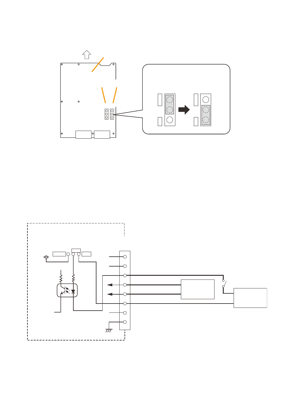
Step 4. Apply 12 – 40 V Dc to Pin 6 of the local Audio control Input terminal (rJ45).
A built-in current limiting resistor of 4.4 kΩ limits the current to 10 mA or less.
-
+
Photo coupler
VCC
SJP901
SJP902
4.4 kΩ
SX-2100AO
Internal circuit
Control input
Local audio control input terminals
(RJ45)
Audio input (H)
Audio input (C)
External power source
1
2
3
4
5
6
7
8
Power supply
Sound source
EXT
INTER
the audio input (Pin Nos. 4 and 5) is
rated at 0 dB* and 10 kΩ.
When connecting a microphone to
this input, use one with a preamplifier.
* 0 dB = 1 V
Step 2. change the jumper settings on the link circuit board.
Note that the SJP901 is for the local Input 1, and the SJP-902 for the local Input 2.
INTER
EXT
INTER
EXT
SX-2100AO link circuit board
Front panel side
Local input 1
SJP901
Note
The figure shows an example for supplying the
power from an external device to Local Input 2.
SJP902
Local input 2
SJP902
SJP902
Using an external
power supply
Using the internal
power supply
(Factory-preset)
Note
the factory-preset wiring differs from the figure above. for details, refer to