Toa SX-2000 Series Installation User Manual
Page 106
106
8
7
6
5
4
3
2
1
TERMINATION
CPU OFF
LEVEL METER
COMMUNICATION
UNIT ID
On
Off
DIP SWITCH
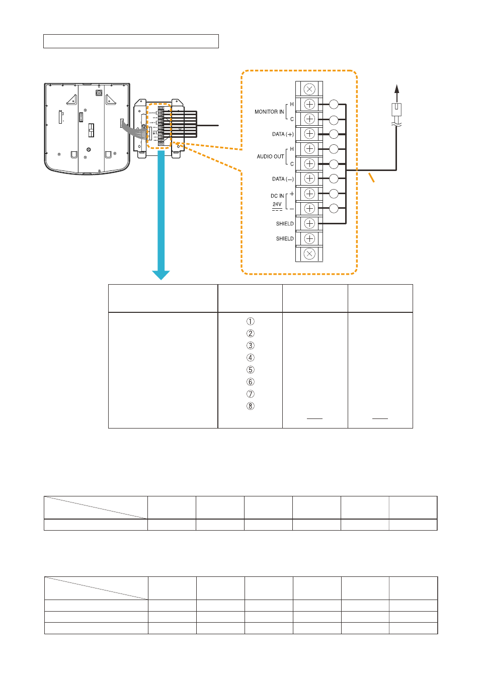
To SX-200RM
MONITOR IN (H)
MONITOR IN (C)
DATA (+)
AUDIO OUT (H)
AUDIO OUT (C)
DATA (-)
DC IN 24 V (+)
DC IN 24 V (-)
SHIELD
Shield
Orange/White
Orange
Green/White
Blue
Blue/White
Green
Brown/White
Brown
Green/White
Green
Orange/White
Blue
Blue/White
Orange
Brown/White
Brown
Wall mount bracket unit
(supplied with the RM-200SF)
RJ45 connector
pin No.
Cable color
(T568B type)
Cable color
(T568A type)
RM-200SF bottom
Wall mount bracket unit
(supplied with the RM-200SF)
Terminal block
Connection cable
(with RJ45 connectors)
1
2
3
4
5
6
7
8
[when power is supplied from the SX-200RM]
• The following table shows the maximum cable distance when STP Category 5 straight cable (with RJ45
connectors) is used.
No. of expansion
units
RM-200SF
alone
RM-200SF +
RM-210 x 1
RM-200SF +
RM-210 x 2
RM-200SF +
RM-210 x 3
RM-200SF +
RM-210 x 4
Cable
STP Category 5
140 m
120 m
100 m
90 m
80 m
RM-200SF +
RM-210 x 5
70 m
• To make longer cable lengths than those shown in the above table, use over 4-pair shielded CPEV cable.
the relationship of the cPEV cable conductor diameter to the maximum cable distance is as follows:
No. of expansion
units
RM-200SF
alone
RM-200SF +
RM-210 x 1
RM-200SF +
RM-210 x 2
RM-200SF +
RM-210 x 3
RM-200SF +
RM-210 x 4
Conductor diameter
ø0.65 mm
230 m
190 m
170 m
150 m
130 m
ø0.9 mm
460 m
380 m
330 m
290 m
260 m
ø1.2 mm
800 m
670 m
570 m
500 m
450 m
RM-200SF +
RM-210 x 5
110 m
230 m
400 m
Connecting the SX-200RM to the RM-200SF