System configuration example 2, Components – Toa SX-2000 Series Installation User Manual
Page 101
101
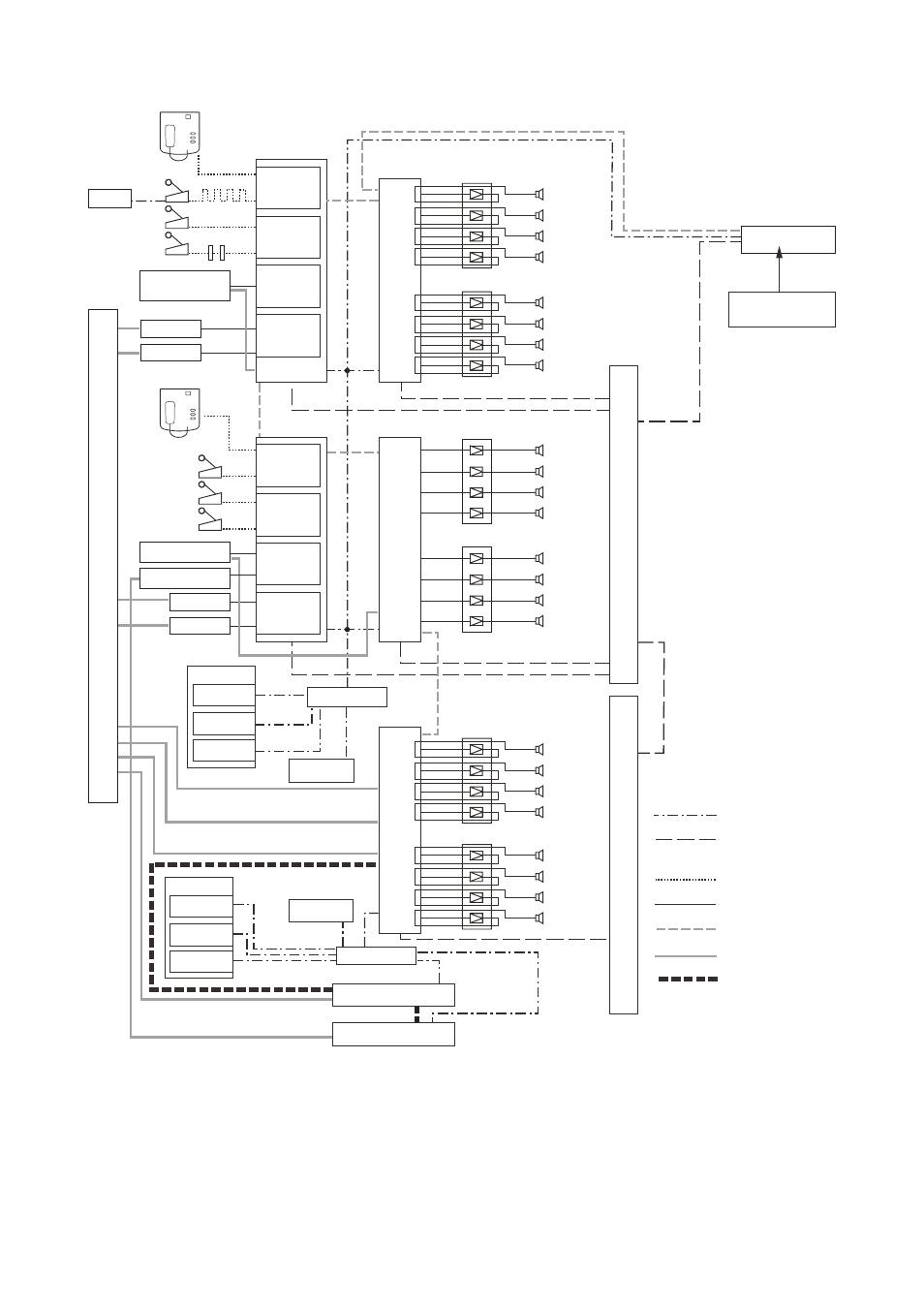
3.2. System Configuration Example 2
RM-200SA
RM-200RJ
RM-200SA
VX-2000DS
VX-2000DS
Battery
Battery
VX-2000PF
VX-200PS
VX-200PS
VX-200PS
VX-2000PF
VX-200PS
VX-200PS
VX-200PS
Power amplifiers
Power amplifiers
Power amplifiers
Power amplifiers
SX-2000SM
BGM1
AD-246
BGM2
SW-HUB
Power (24 V DC)
SX link
(A, B 2 lines)
RM link
Audio
Analog link
Contact control
CI/CO link
SX-2100AO
SX-2100AI
RM-200SF
RM-200SF
Zone 2
Zone 3
Zone 4
Zone 5
Zone 6
Zone 7
Zone 8
Zone 1
SX-200RM
SX-200RM
D-922E
D-936R
BGM1
BGM2
SX-2000AO
SX-2000AI
Zone 10
Zone 11
Zone 12
Zone 13
Zone 14
Zone 15
Zone 16
Zone 9
SX-2100AO
SX-2000CO
SX-2000CI
Zone 18
Zone 19
Zone 20
Zone 21
Zone 22
Zone 23
Zone 24
Zone 17
SX-200RM
SX-200RM
D-922E
D-936R
SW-HUB
Programable Time
r
Digital announcer
Power amplifiers
Power amplifiers
Control input
Control
input
Control
input
Control
input
Control
input
CF card
(Setting/Log data)
Digital announcer
Digital announcer
Control input
Control output
[Components]
rm-200Sf: fireman's microphone
rm-200SA: remote microphone
rm-200rJ: terminal unit
AD-246:
Ac adapter
SX-2000AI: Audio input unit
SX-2100AI: Audio input unit
SX-200rm: remote microphone interface module
SX-2000cI: control input unit
D-922E:
microphone/line input module
D-936r:
Stereo input module
SX-2000Ao: Audio output unit
SX-2100Ao: Audio output unit
SX-2000Sm: System manager
SX-2000co: control output unit
VX-2000DS: Emergency power supply
VX-200PS: Power supply unit
VX-2000Pf: Power supply frame