Toa SX-2000 Series Installation User Manual
Page 31
31
51. Local Audio Control Input Terminals
[LOCAL AUDIO IN 1/IN 2]
Audio signals fed to these terminals are broadcast
to only the zones that this unit covers.
Each terminal is equipped with a control input,
which allows local broadcasts to be made.
It is possible to isolate the control input from this
unit by changing the internal jumper setting. (See
for details.)
Input "IN1" has a higher priority than Input "IN2."
If the control input terminal of "IN1" is activated
while broadcast is made through the "IN2," the
broadcast is interrupted and changed to the
broadcast through the "IN1."
the local input has a lower priority than the BGm
or general-purpose sound sources. Activating the
emergency broadcasts to a part of zones where
local broadcasts are currently in progress causes
all local broadcasts to terminate.
52. Functional Earth Terminal [SIgNAL gND]
Hum noise may be generated when external
equipment is connected to the unit. connecting
this terminal to the functional earth terminal of the
external equipment may reduce the hum noise.
Note: this terminal is not for protective earth.
53. Standby Amplifier Input Terminal
[STANDBY AMp]
connect this terminal to the speaker output
terminal of the standby amplifier*
1
.
*
1
use the VP-2000 series or VP-3000 series
amplifier.
54. Speaker Connection Terminals
[ZONE 1 – 8 Sp]
connect these terminals to speakers.
55. Amplifier Input Terminals [ZONE 1 – 8 AMP]
connect these terminals to the speaker output
terminals of the power amplifiers for zone output.
56. Analog Link Output Terminal
[ANALOg LINK OUT]
connect this terminal to the analog link input
terminal of the SX-2000AI, SX-2100AI, SX-
2000Ao, or SX-2100Ao.
57. Analog Link Input Terminal
[ANALOg LINK IN]
connect this terminal to the analog link output
terminal of the SX-2000Sm, SX-2000AI, SX-
2100AI, SX-2000Ao, or SX-2100Ao.
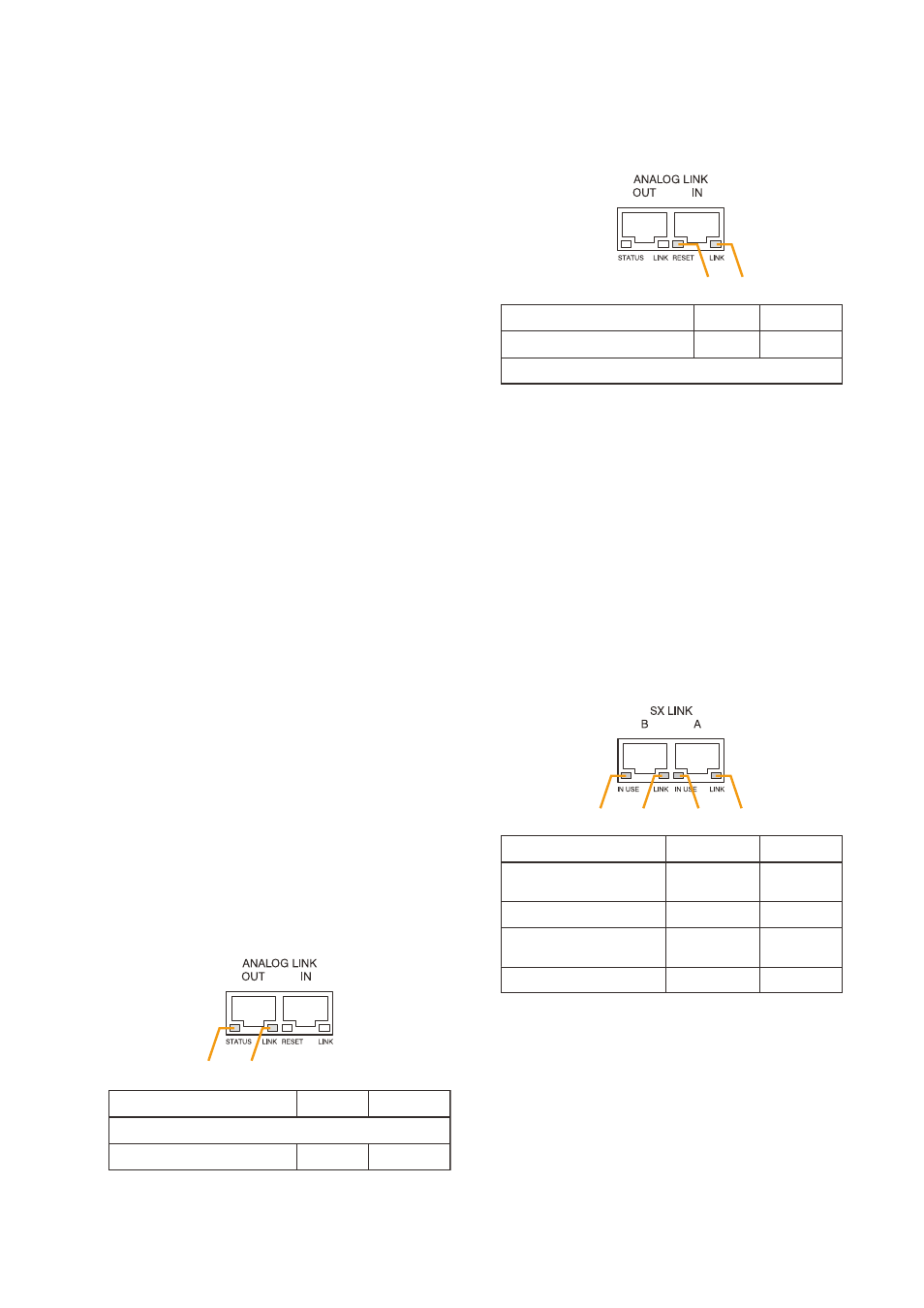
58. SX Link Terminals [SX LINK A/B]
use switching hubs to connect between the SX
link terminals of the SX-2000Sm, SX-2000AI, SX-
2100AI, SX-2000Ao, and SX-2100Ao.
connect each of the SX links A and B to the
same switching hub*
2
, or to different switching
hubs*
2
that have been cascade connected.
Notes
• Be sure to connect both terminals of A and B.
• After connection completion, press the Reset
key to reactivate the SX-2100Ao.
*
2
contact your toA dealer for more information
on switching hubs.
59. MAC Address
mAc address to be used for SX link connection.
1
2
Function
LED On
LED Off
1. Not used
2. OUT connection confirmation Connected Unconnected
3
4
Function
LED On
LED Off
4. Not used
3. RESET input
Resetting
Normal
1
2
3
4
Function
LED On/Flashing
LED Off
2. B connection confirmation
Connected
Unconnected
1. B operation in progress
indication
Operating
Not operating
4. A connection confirmation
Connected
Unconnected
3. A operation in progress
indication
Operating
Not operating
SX-2100AO