Minimum configuration – Toa SX-2000 Series Installation User Manual
Page 187
187
RM-200SA
System manager
SX-2000SM
RM-200SA
(general mode)
(1)
(2)
(3)
(4)
(5)
(6) (7)
(8)
(9)
(10)
(11)
2.3. Examples for the Mandatory Indications and Controls
2.3.1. Minimum configuration
the minimum requirements are listed in chapter 2.1 from no. 1 to 7. the installation shall be made in a room of
access level 1 and no front door of the cabinet rack shall prevent a quick access to the indication and control
units. the remote microphone shall be installed adjacent to the cabinet rack containing the system manager
SX-2000Sm. When several cabinet racks are installed adjacent to each other and one of them containing the
system manager, then the remote microphone can be installed adjacent to another cabinet rack in that group.
the best place would be next to the system manager to see all indications together.
the remote microphone must not contain any emergency related function or a fault reset button (refer to
chapter 3.1 and 3.2). When paging shall be provided, then the remote microphone must be of general type, i.e.
the rm-200SA in general mode because paging must not be available when the system is in emergency mode.
In this case no emergency related function can be set as required by access level 1. We recommend to use the
rm-200SA in general mode to avoid setting of emergency controls.
minimum configuration:
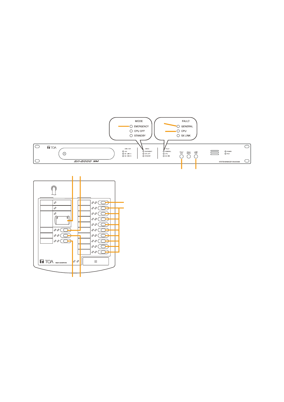
Figure 1: Minimum configuration for mandatory indications and controls
(1) indication of VA condition (emergency mode)
(2) general fault indication
(3) system (cPu) fault indication
(4) fault acknowledge for (2) - (3) and (7) - (9)
(5) lamp test button
(6) when the rm-200SA is set to be a general microphone, then this button cannot be programmed. Its
related lED indicates the VA condition (emergency mode).
(7) power supply fault (fault receipt programming)
(8) fuse rupture (fault receipt programming)
(9) only when the system is installed in more than one location: fault in a signal path between decentralised
system racks (fault receipt programming);
otherwise the lamp test can be assigned to this button
(10) lamp test (if not set on (9))
(11) no function (may be used for non-emergency related functions as paging etc.)