Toa SX-2000 Series Installation User Manual
Page 18
18
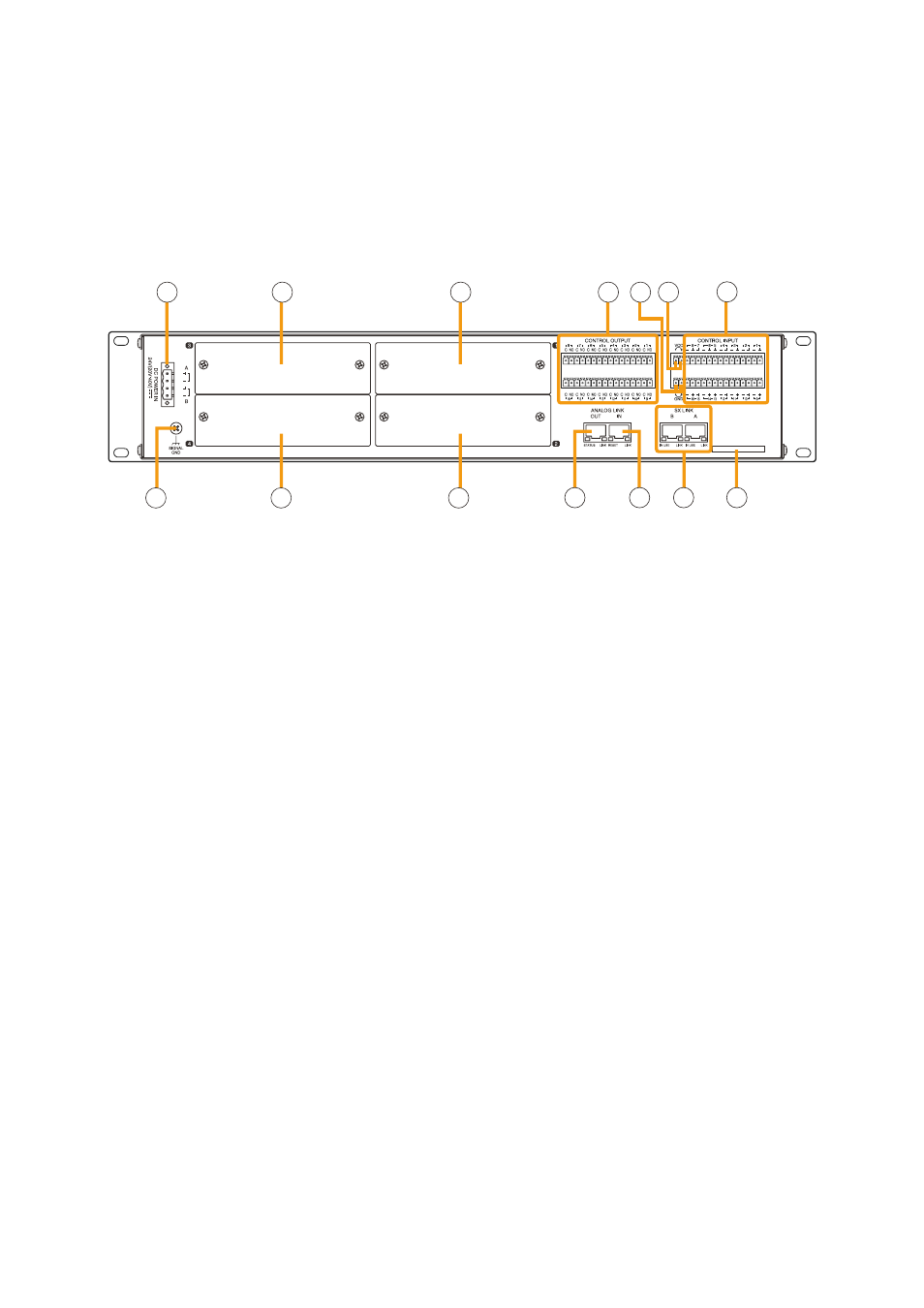
[Rear]
38
37
39
40
41
42
47
48 49
43 44
50
45
46
37. DC power Input Terminal [DC pOwER IN]
connect an optional Dc power supply unit to
this terminal. Select the Dc power supply source
with consideration given to the current power
consumption of the system the SX-2100AI is to be
connected to. When not using a redundant power
system*, connect the [+] terminal of input A to the
[+] terminal of input B, and the [–] terminal of input
A to the [–] terminal of input B.
(refer to the Instruction manual attached to the
VX-2000DS/3000DS.)
*
A method of connecting separate power
sources to each power input or connecting the
commercial power supply and backup power
supply separately to each power input to prevent
the system from going down when a cable is
broken or power fails.
38. Module Slot 3 [3]
Slot for input channels 5 and 6.
39. Module Slot 1 [1]
Slot for input channels 1 and 2.
40. Functional Earth Terminal [SIgNAL gND]
Hum noise may be generated when external
equipment is connected to the unit. connecting
this terminal to the functional earth terminal of the
external equipment may reduce the hum noise.
Note: this terminal is not for protective earth.
41. Module Slot 4 [4]
Slot for input channels 7 and 8.
42. Module Slot 2 [2]
Slot for input channels 3 and 4.
43. Control Output Terminals
[CONTROL OUTpUT 1 – 16]
relay make contact outputs.
All the contact outputs are of normally open type
when shipped from the factory.
Each output can be converted into normally closed
type by changing the internal jumper setting. (See
"operation of Power feed Jumper and Isolation
.)
Each contact capacity is rated at 40 V Dc for
withstand voltage, and 2 mA – 300 mA for control
current. these terminals are controlled by the SX-
2000 Setting Software. (See the separate Setting
Software Instructions, "Pattern Settings.")
44. Isolation Jumper [gND]
the supplied removable terminal plug is equipped
with a jumper. When the jumper is attached, the
[–] terminals of all inputs (1 – 16) are connected to
the internal power supply. removing the jumper
disconnects and isolates these [–] terminals from
this unit. (See
"operation of Power feed Jumper
and Isolation Jumper" on the next page
.)
45. power Feed Jumper [vCC]
the supplied removable terminal plug is equipped
with a jumper. When the jumper is attached, the
circuits of all control inputs (1 – 16) are powered
from inside the SX-2100AI. removing the jumper
disconnects this internal power supply and thus
requires that power be supplied externally to the
circuit. (See
"operation of Power feed Jumper
and Isolation Jumper" on the next page
.)
SX-2100AI
33.
Remote Microphone Connection Status
Indicator
the device number of the remote microphone
connected to the SX-2100AI lights.
34. Monitor Level Meter
Indicates the sound volume level of the input
channel being monitored.
35. Monitor Level Meter Scale
lights when the monitor oN/off key (15) is set
to oN.
36. Monitor ON/OFF Indicator [LEvEL]
lights when the monitor oN/off key (15) is set
to oN.