Configuration with, Indication, Faults – Toa SX-2000 Series Installation User Manual
Page 188: Zones
188
RM-200SA
System manager
SX-2000SM
RM-200SA
(general mode)
(1)
(2)
(3)
(4)
(5) (6)
(7)
(8)
(9)
(10)
(18)
(17)
(16)
(15)
(14)
(13)
(12)
(11)
2.3.2. Configuration with indication of faults in vA zones
In this example, the minimum requirements listed in chapter 2.1 from no. 1 to 7 are expanded by the fault
indications of VA zones. the installation shall be made in a room of access level 1 and no front door of the
cabinet rack shall prevent a quick access to the indication and control units. the remote microphone shall
be installed adjacent to the cabinet rack containing the system manager SX-2000Sm. When several cabinet
racks are installed adjacent to each other and one of them containing the system manager, then the remote
microphone can be installed adjacent to another cabinet rack in that group. the best place would be next to
the system manager.
the remote microphone must not contain any emergency related function or a fault reset button (refer to
chapter 3.1 and 3.2). When paging shall be provided, then the remote microphone must be of general type,
i.e. the rm-200SA in general mode. We recommend to use the rm-200SA in general mode to avoid setting of
emergency controls.
When applying the fault indication of VA zones (option with requirement, refer to item 9 of chapter 2.2), then
- add surveillance on all VA related outputs
- assign each output of the same VA zone to one failure pattern, i.e. one failure pattern per VA zone
- assign each failure pattern to its own fault receipt button of the indicating remote microphone
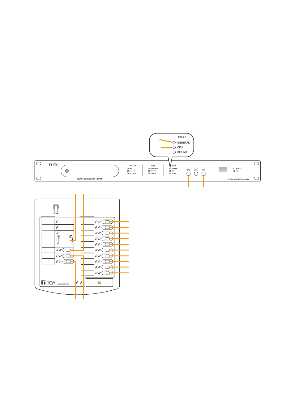
Figure 2: Configuration with mandatory Indications and Indication of faults in VA Zones
(explanation on
)
(1) general fault indication
(2) system (cPu) fault indication
(3) fault acknowledge for (1) and (2)
(4) lamp test button
(5) do not program! (only emergency functions that must be in access 2 can be programmed) Its related lED
indicates the VA condition.
(6) power supply fault (fault receipt programming)
(7) fuse rupture (fault receipt programming)
(8) fault in a signal path between the decentralised system racks (fault receipt programming)