Toa SX-2000 Series Installation User Manual
Page 65
65
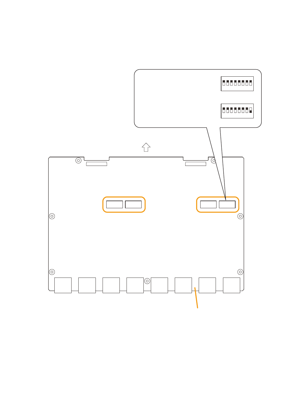
Step 2. Perform DIP switch settings on the co circuit board.
the control output channels correspond to the DIP switches on the co circuit board as follows.
control output channels 1 – 8:
SW301
control output channels 9 – 16:
SW302
control output channels 17 – 24:
SW303
control output channels 25 – 32:
SW304
CN201
CN101
CN308
CN307
CN306
CN305
CN304
CN303
CN302
CN301
SW301
SW302
SW303
SW304
SX-2000CO
CO circuit board
Front panel side
This setting causes the control output
channels 1 – 8 to remain OFF when
the general urgency all-call is made.
(Factory-preset).
This setting causes the control output
channel 1 to be turned ON when the
general urgency all call is made.
1
2
3
4
5
6
7
8
ON
1
2
3
4
5
6
7
8
ON
Step 3. replace the top panel.
Note
Note the specific shapes of the different screws when replacing the top panel. (See Step 1.)