Toa SX-2000 Series Installation User Manual
Page 13
13
33.
Remote Microphone Connection Status
Indicator
the device number of the remote microphone
connected to the SX-2000AI lights.
34. Monitor Level Meter
Indicates the sound volume level of the input
channel being monitored.
35. Monitor Level Meter Scale
lights when the monitor oN/off key (15) is set
to oN.
36. Monitor ON/OFF Indicator [LEvEL]
lights when the monitor oN/off key (15) is set
to oN.
[Rear]
38
37
39
40
41
42
43
44
45
46
37. DC power Input Terminal [DC pOwER IN]
connect an optional Dc power supply unit to
this terminal. Select the Dc power supply source
with consideration given to the current power
consumption of the system the SX-2000AI is to be
connected to. When not using a redundant power
system*, connect the [+] terminal of input A to the
[+] terminal of input B, and the [–] terminal of input
A to the [–] terminal of input B.
(refer to the Instruction manual attached to the
VX-2000DS/3000DS.)
*
A method of connecting separate power
sources to each power input or connecting the
commercial power supply and backup power
supply separately to each power input to prevent
the system from going down when a cable is
broken or power fails.
38. Module Slot 3 [3]
Slot for input channels 5 and 6.
39. Module Slot 1 [1]
Slot for input channels 1 and 2.
40. Functional Earth Terminal [SIgNAL gND]
Hum noise may be generated when external
equipment is connected to the unit. connecting
this terminal to the functional earth terminal of the
external equipment may reduce the hum noise.
Note: this terminal is not for protective earth.
41. Module Slot 4 [4]
Slot for input channels 7 and 8.
42. Module Slot 2 [2]
Slot for input channels 3 and 4.
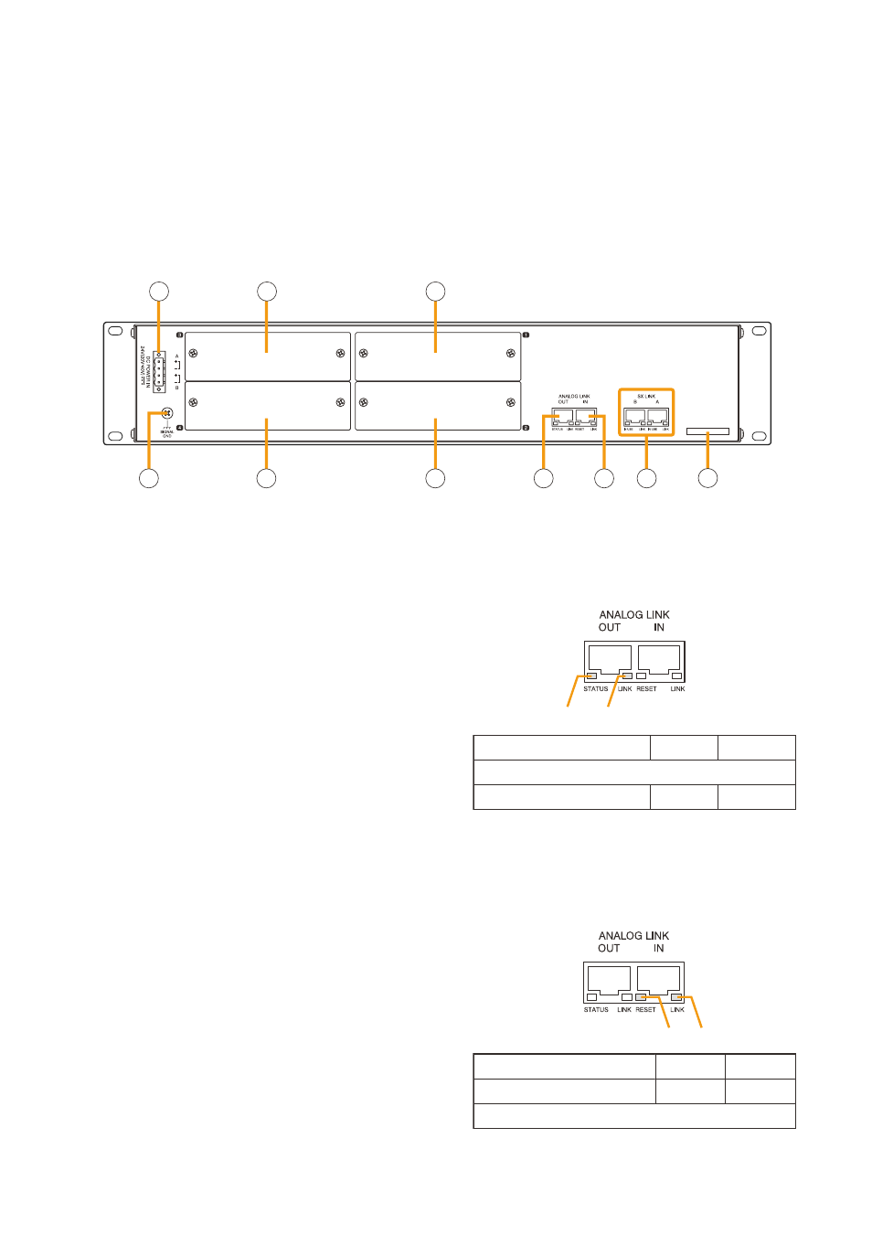
43. Analog Link Output Terminal [ANALOg LINK
OUT]
connect this terminal to the analog link input
terminal of the SX-2000AI, SX-2100AI, SX-
2000Ao, or SX-2100Ao.
44. Analog Link Input Terminal [ANALOg LINK IN]
connect this terminal to the analog link output
terminal of the SX-2000Sm, SX-2000AI, SX-
2100AI, SX-2000Ao, or SX-2100Ao.
1
2
Function
LED On
LED Off
1. Not used
2. OUT connection confirmation Connected Unconnected
3
4
Function
LED On
LED Off
4. Not used
3. RESET input
Resetting
Normal
SX-2000AI