Rm-200rj terminal unit, Rm-200rj, Terminal – Toa SX-2000 Series Installation User Manual
Page 43: Unit
43
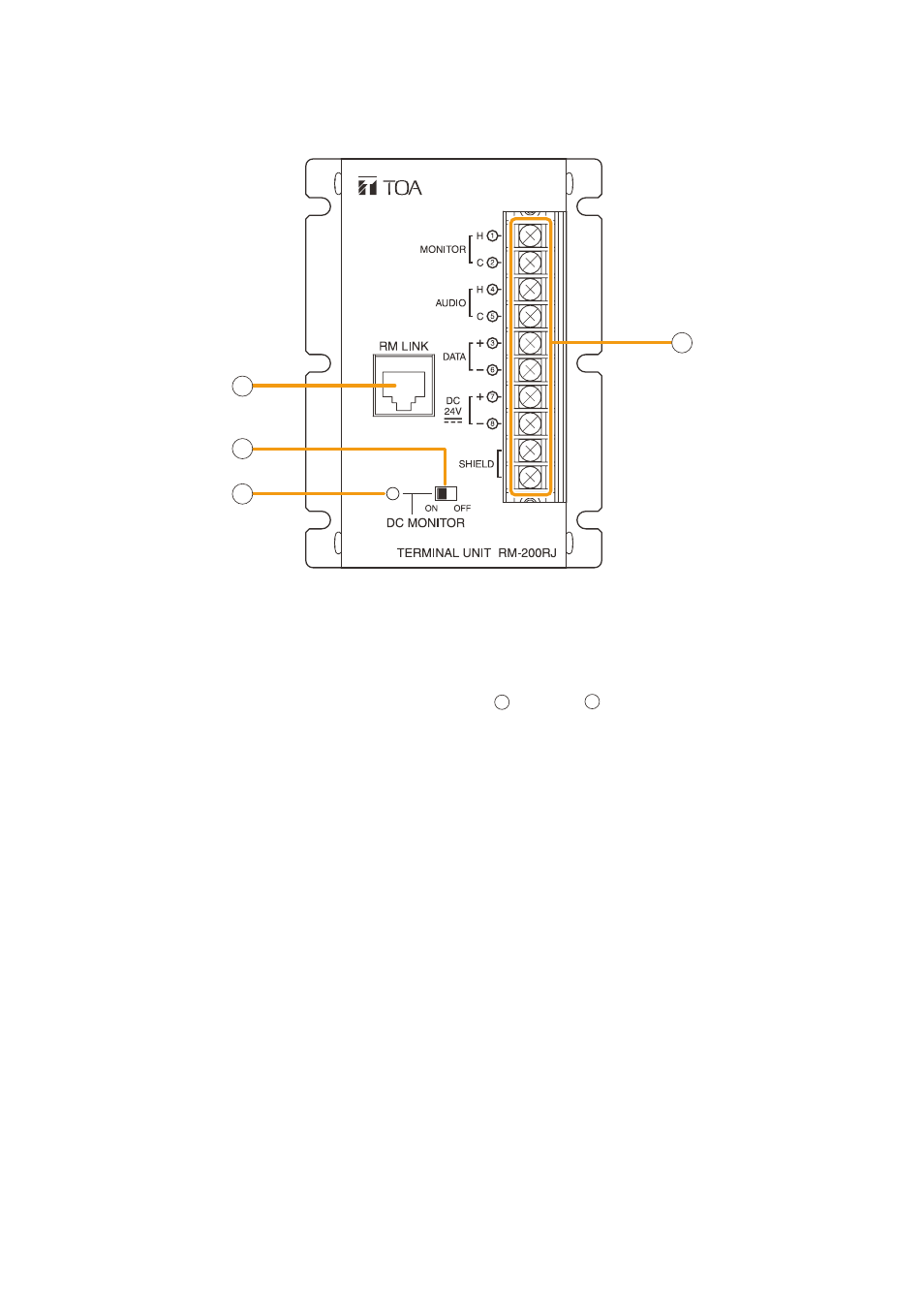
1.11. RM-200RJ Terminal Unit
[Front]
1. RM Link Terminal [RM LINK]
connect to the rm link terminal of the rm-200SA
or SX-200rm.
2. power Monitor Switch [ON/OFF]
Set to oN to enable the Power monitor Indicator.
(factory-preset: oN)
3. power Monitor Indicator (green)
lights if the source voltage of the Dc power input
exceeds the minimum operating voltage of the rm-
200SA when the Power monitor Switch is set to
oN.
4. Screw Terminal Block
the Screw terminal block and rm link terminal
are internally connected in parallel. Numbers
1
through
8
indicated beside each terminal
correspond to the pin numbers of the rJ45
connector to be connected to the rm link terminal
(1).
• Audio monitor terminals [MONITOR H/C]
connect the audio monitor line from the SX-2000
system to the rm-200SA.
• Audio output terminals [AUDIO H/C]
connect the audio output line from the rm-
200SA to the SX-2000.
• RM communication terminals [DATA +/–]
connect the control communication line between
the SX-2000 system and the rm-200SA.
• DC power input terminals [DC 24 V +/–]
used to supply Dc power from the SX-2000
system to the rm-200SA.
• Shield terminals [SHIELD]
connect the shield wires for noise reduction or
for system control.
Be sure to connect at least one shield wire.
1
2
3
4