System configuration example, System configuration example 1 – Toa SX-2000 Series Installation User Manual
Page 100
100
3. SYSTEM CONFIgURATION EXAMpLE
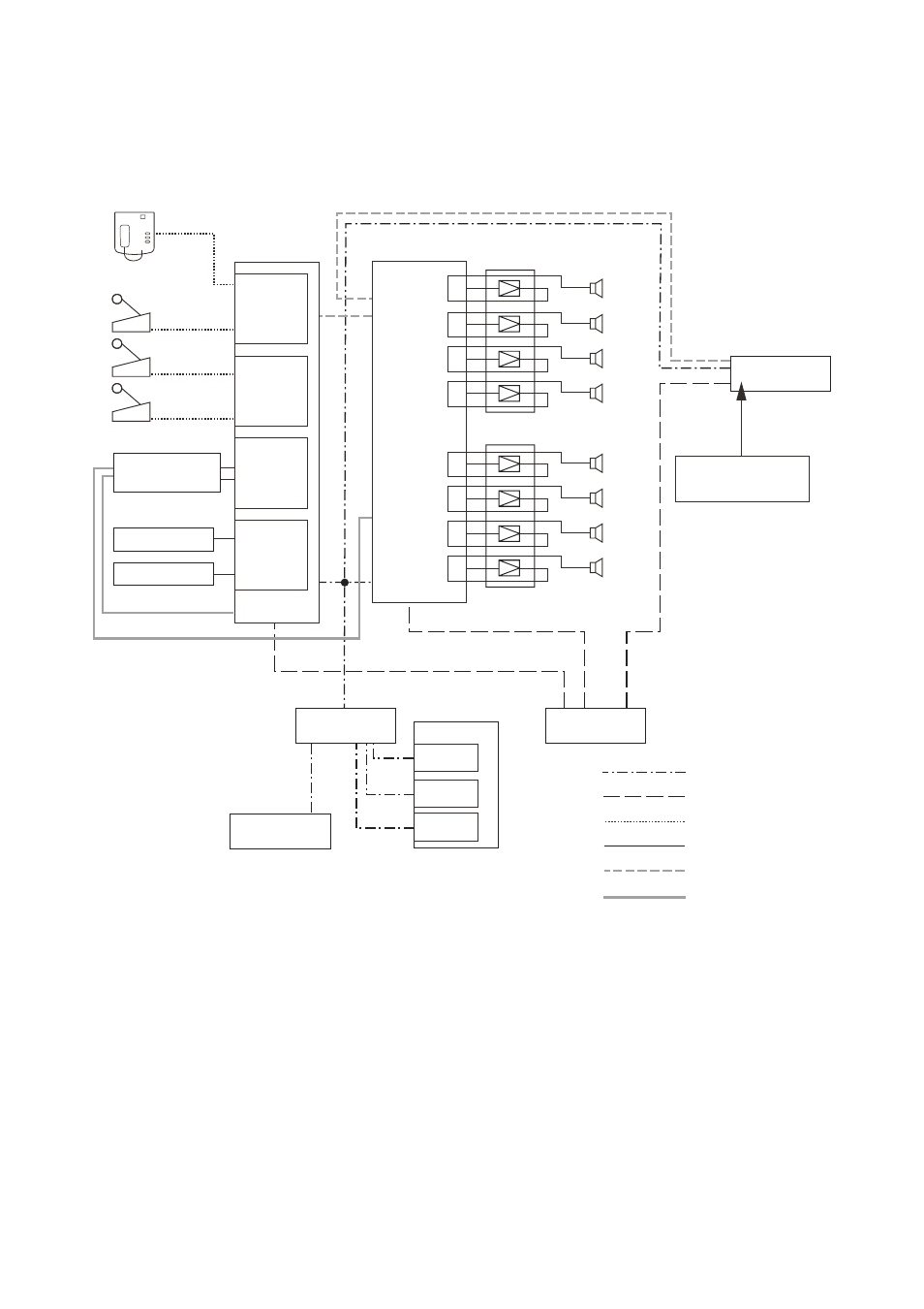
3.1. System Configuration Example 1
SX-2000SM
CF card
(Setting/Log data)
VX-2000DS
BGM 1
Digital announcer
BGM 2
SW-HUB
Battery
Power (24 V DC)
SX link (A, B 2 lines)
RM link
Audio
Analog link
Contact control
Power amplifiers
Power amplifiers
SX-2100AO
Control
input 2
Control input 1
SX-2100AI
RM-200SA
RM-200SF
Zone 2
Zone 3
Zone 4
Zone 5
Zone 6
Zone 7
Zone 8
Zone 1
SX-200RM
SX-200RM
D-922E
D-936R
VX-2000PF
VX-200PS
VX-200PS
VX-200PS
[Components]
rm-200Sf: fireman's microphone
rm-200SA: remote microphone
SX-2100AI: Audio input unit
SX-200rm: remote microphone interface module
D-922E:
microphone/line input module
D-936r:
Stereo input module
SX-2100Ao: Audio output unit
SX-2000Sm: System manager
VX-2000DS: Emergency power supply
VX-200PS: Power supply unit
VX-2000Pf: Power supply frame