Rm-200sa expansion with the addition of the rm-210, Installed on a flat surface), P. 81 – Toa SX-2000 Series Installation User Manual
Page 81
81
2.5.9. RM-200SA expansion with the addition of the RM-210 (Installed on a flat surface)
When adding an rm-210 remote microphone Extension to expand the rm-200SA, use the rm-210's Extension
cable and included linkage Bracket to link the 2 microphones.
After DIP switch setting completion, follow the procedures below.
[Mounting hardware (supplied with the RM-210)]
linkage Bracket A ................................ 2
linkage Bracket B ................................ 1
Screw ................................................. 12
Step 1. turn over both the rm-200SA and the rm-210, and keep them in close contact with each other.
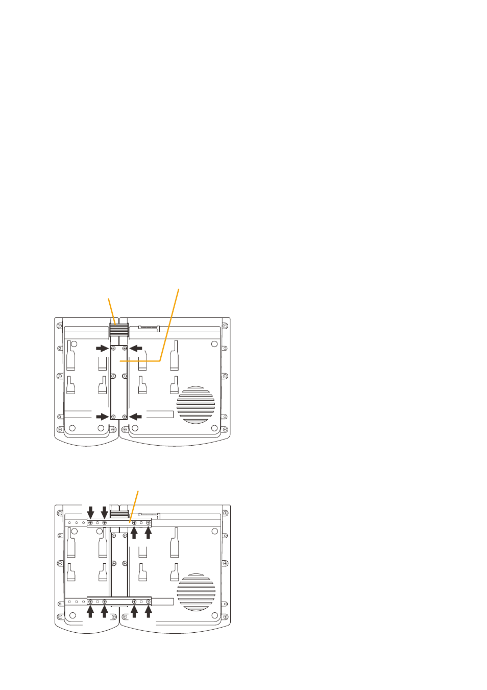
Step 2. connect between both units using the extension cable supplied with the rm-210.
Step 3. using 4 supplied screws indicated by arrows and linkage Bracket B, link both units together.
Step 4. Using 8 supplied screws indicated by arrows and 2 pieces of Linkage Bracket A, fix both units securely.
Note: to add another rm-210 to the installed rm-210, use the similar procedures as in this section.
Extension cable
(Supplied with RM-210)
RM-210
RM-200SA
Linkage Bracket B
3
2
[Bottom side]
Linkage Bracket A
RM-210
RM-200SA
[Bottom side]
4
Notes
• Because the linkage Bracket A is provided with 2
spare screw holes, use them to link the 2 units if the
designated screw threaded holes are damaged.
• If incorrect or loose connection is found between
both units, loosen all the bracket fixing screws to
disassemble the units and then link them again with
the screws.