Fluorescent display – Toa SX-2000 Series Installation User Manual
Page 12
12
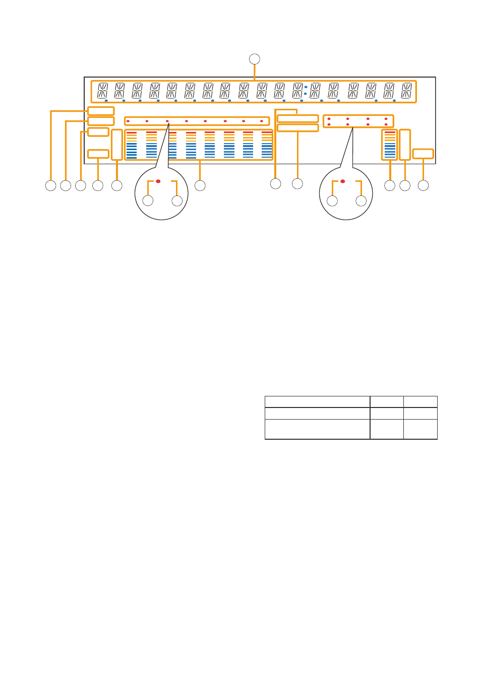
[Fluorescent Display]
COM
FAULT
KEYLOCK
OL
0
–10
–20
–30
–40
OL
0
–10
–20
–30
–40
FADER
LEVEL
LEVEL
1
2
3
4
5
6
7
8
1
2
3
4
5
6
7
8
EMERGENCY
22 23
26
30
29
24 25
21
34 35 36
3
3
27
28
6
6
31
32
33
Notes
• A timer-activated light shutoff function can be set for the fluorescent display using the SX-2000 Setting
Software. (See the separate Setting Software Instructions, "Basic Settings.")
When the light shutoff function has been set, if the SX-2000AI is not operated for 5 minutes or more, the
fluorescent display's light goes off and the standby indicator (11) begins to flash. Pressing any keys other than
the function keys on the front panel resets the screen display.
• Normally, the fluorescent display's light goes off at the time of the power failure.
• While the SX-2000 system is in an emergency condition, the fluorescent display's light does not go off even
if the power fails.
SX-2000AI
function assigned to the channel key When oN When off
Input oN/off
lights*
unlit
General-purpose pattern broadcast's
activation and termination
flashes
lights
21. Text Display Area
Displays the menu screen information when the
corresponding function key is pressed.
22. COM Indicator [COM]
flashes to indicate a communications error.
23. Fault Indicator [FAULT]
flashes when a system failure, incorrect system
configuration* or communications error is detected.
This indicator continues to flash until failure
conditions return to normal.
* When the system or module configuration differs
from the contents set by the SX-2000 Setting
Software.
24. Input Level Meter Fader Indicator [FADER]
lights when the input level meter indicates the
sound volume set using the SX-2000 Setting
Software or input volume control.
25. Input Level Meter Level Indicator [LEvEL]
lights when the input level meter indicates the
level being input to the SX-2000AI.
26. Input Level Meter Scale
27. Input Indicator
the input channel to be monitored lights red.
28. Input ON/OFF Indicator
Indicates the unit’s operating status when the
corresponding channel key is pressed.
the indicator state differs depending on the
function assigned to each channel key as follows.
* the indicator state is "unlit" when the input volume is muted.
29. Input Level Meter
Indicates the actual level or a set volume value on
each input channel.
30. Key Lock Indicator [KEY LOCK]
lights when the input volume controls and
channel keys are locked. (See
)
31. Emergency Indicator [EMERgENCY]
lights when the SX-2000 system is in an
emergency condition.
32. Remote Microphone Output Status Indicator
lights red continuously as long as announcements
are made from the rm-200Sf, rm-200SA, or
rm-210 remote microphone.