Warning – Toa SX-2000 Series Installation User Manual
Page 79
79
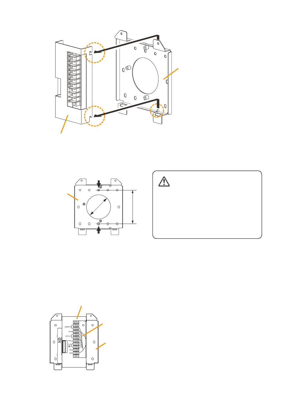
(2) Slide the Bracket A as show below to detach it from the Bracket B.
Bracket A
Bracket B
Slide the Bracket A upward, then pull it toward you.
(3) Attach the Bracket B to the electrical box using 2 screws m3.5 x 20 supplied with the rm-200Sf.
Screw holes for mounting to
the electrical box (2 places)
Unit: mm
Bracket B
83.5
ø60
• Install the unit only in a location that can
structurally support the weight of the
unit and the mounting bracket. Doing
otherwise may result in the unit falling
down and causing personal injury and/or
property damage.
• Be sure to use 2 screws when mounting
the bracket to the electrical box.
(4) replace the Bracket A.
reverse the procedures (1) and (2) above.
Note
take care not to pinch the routed link cable between the Brackets A and B.
Step 2. connect the link cable to the screw terminal block.
Note
Put the link cable inside the Bracket A after
connection completion.
Do not allow the link cable to protrude.
the cable may be damaged if it protrudes when the
bracket unit is installed onto the wall.
Wall mount bracket unit
(supplied with the RM-200SF)
Link cable
Bracket A
Bracket B
wARNINg