Toa SX-2000 Series Installation User Manual
Page 138
138
IMpORTANT
In both Impedance method and Eol method described below, be sure to make the speaker line initial setting
after connection completion when the speaker line surveillance is to be performed.
[Impedance method]
the cable connection in this method is the same as when the surveillance function is not used. (See
to use the surveillance function, make the necessary setting on the SX-2000 Setting Software.
Notes
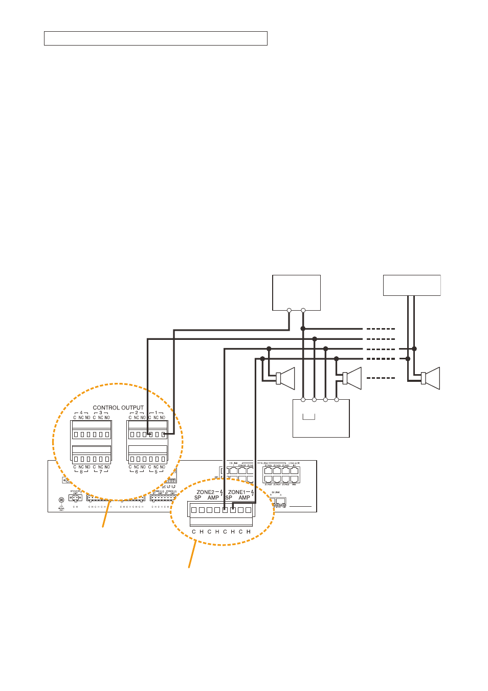
• The attenuator shown in the diagram below is assumed to be bypassed when DC voltage is applied to the
attenuator control line.
• The zone numbers coincide with the control output numbers.
• Set the application of the control output that connects an attenuator to "ATTENUATOR" on the SX-2000
Setting Software. for the setting procedures, refer to the separate Setting Software Instructions.
• When an emergency broadcast is made, the attenuators are bypassed. To use emergency broadcast and
speaker line surveillance function, make necessary settings on the SX-2000 Setting Software. (See the
separate Setting Software Instructions, "Basic settings.")
[EOL method]
(–)
Relay
Control
(+) N SP
(–)
DC POWER
Supply
(+)
End-of-line unit
SX-2100AO
8P removable terminal plug
(supplied with the SX-2100AO)
6P removable terminal plug
(supplied with the SX-2100AO)
Control output terminals
Control output relay contact capacity
Withstand voltage: 40 V DC
Contact current: 0.3 A
Speaker connection terminals
and amplifier input terminals
Note
the speaker line with attenuators installed cannot be detected for its open-circuit state with the Speaker line
Surveillance function.
Connection between the SX-2100AO and attenuators