Fluorescent display – Toa SX-2000 Series Installation User Manual
Page 22
22
COM
FAULT
KEYLOCK
EMERGENCY
OL
0
–10
–20
–30
–40
OL
0
–10
–20
–30
–40
FADER
LEVEL
LEVEL
1
2
3
4
5
6
7
8
1
2
21
22 23 24 25 26
29
30
31 32 33
34 35 36
3
3
27
28
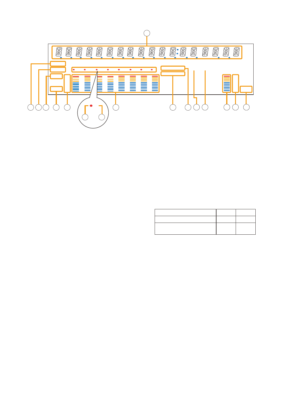
21. Text Display Area
Displays the menu screen information when the
corresponding function key is pressed.
22. COM Indicator [COM]
flashes to indicate a communications error.
23. Fault Indicator [FAULT]
flashes when a system failure, incorrect system
configuration*1 or communications error is
detected. This indicator continues to flash until
failure conditions return to normal.
*
1
When the system or module configuration
differs from the contents set by the SX-2000
Setting Software.
24. Output Level Meter Fader Indicator [FADER]
lights when the output level meter indicates the
sound volume set using the SX-2000 Setting
Software or output volume control.
25. Output Level Meter Level Indicator [LEvEL]
lights when the output level meter indicates the
level being output from the SX-2000Ao.
26. Output Level Meter Scale
27. Output Indicator
the output channel to be monitored lights red.
28. Output ON/OFF Indicator
Indicates the unit's operating status when the
corresponding channel key is pressed.
the indicator state differs depending on the
function assigned to each channel key as follows.
* the indicator state is "unlit" when the output volume is muted.
29. Output Level Meter
Indicates the actual level or a set volume value on
each output channel.
30. Emergency Indicator [EMERgENCY]
ights when the SX-2000 system is in an emergency
condition.
When the 24 V emergency cutoff input*
2
is
enabled, this indicator flashes if the input receives
an emergency signal.
*
2
the SX-2000Ao has a 24 V emergency
cutoff input terminal (49) on the rear panel,
allowing control of an emergency audio input.
When the SX-2000 system is combined with
an emergency broadcast system, a 24 V
Dc is normally kept being supplied to this
emergency cutoff input terminal and is cut off
(24 V emergency cutoff function) in emergency
situations. this interrupts the general-purpose
broadcast from the SX-2000 system, allowing
the emergency broadcast system to override it.
(for details, see
.)
Notes
• A timer-activated light shutoff function can be set for the fluorescent display using the SX-2000 Setting
Software. (See the separate Setting Software Instructions, "Basic Settings.")
When the light shutoff function has been set, if the SX-2000Ao is not operated for 5 minutes or more, the
fluorescent display's light goes off and the standby indicator (11) begins to flash. Pressing any keys other than
the function keys on the front panel resets the screen display.
• Normally, the fluorescent display's light goes off at the time of the power failure.
• While the SX-2000 system is in an emergency condition, the fluorescent display's light does not go off even
if the power fails.
SX-2000AO
[Fluorescent Display]
function assigned to the channel key When oN When off
output oN/off
lights*
unlit
General-purpose pattern broadcast’s
activation and termination
flashes
lights