Rear – Toa SX-2000 Series Installation User Manual
Page 33
33
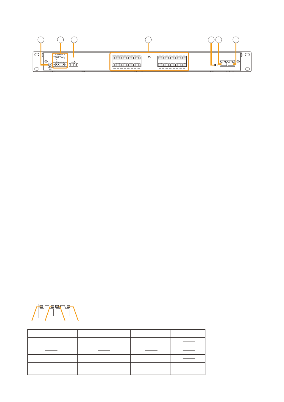
SX-2000CI
[Rear]
DC 24V OUT
MAX. 0.1A
1
2
3
4
5
6
7
8
9
10
11
12
13
14
15
16
17
18
19
20
21
22
23
24
25
26
27
28
29
30
31
32
CONTROL
ON
OFF
CI/CO LINK
THROUGH DATA
INPUT
10
11 12
14 15
16
13
10. Functional Earth Terminal [SIgNAL gND]
Hum noise may be generated when external
equipment is connected to the unit. connecting
this terminal to the functional earth terminal of the
external equipment may reduce the hum noise.
Note: this terminal is not for protective earth.
11. DC power Input Terminal [DC power In]
connect an optional Dc power supply unit to
this terminal. Select the Dc power supply source
with consideration given to the current power
consumption of the system the SX-2000cI is to
be connected to. When not using a redundant
power system*, connect the [+] terminal of input A
to the [+] terminal of input B, and the [–] terminal
of input A to the [–] terminal of input B. (refer
to the Instruction manual attached to the VX-
2000DS/3000DS.)
*
A method of connecting separate power
sources to each power input or connecting the
commercial power supply and backup power
supply separately to each power input to prevent
the system from going down when a cable is
broken or power fails.
12. 24 v DC Output Terminal [DC 24 v OUT]
this terminal supplies 24 V Dc, max. 100 mA to
connected external equipment.
13. Control Input Terminals
[CONTROL INput 1 – 32]
Photo coupler inputs. A current of approximately
2 mA flows when shorted, and the voltage
becomes approximately 24 V Dc when opened.
functions can be assigned to these terminals
using the SX-2000 Setting Software. (See the
separate Setting Software Instructions, "Event
Settings.")
14. CI/CO Link Through Switch [ON/OFF]
Set to oN when using the cI/co link through
terminal (15). (factory-preset: off)
15. CI/CO Link Through Terminal
[CI/CO LINK ThROUgh]
connect this terminal to the cI/co link Data
terminal of the SX-2000co.
refer to the table below for the indicators'
functions and status.
16. CI/CO Link Data Terminal [CI/CO LINK DATA]
connect this terminal to the cI/co link terminal
of the SX-2000Ao or SX-2100Ao, or cI/co link
through terminal of the SX-2000co.
refer to the table below for the indicators'
functions and status.
Functions
LED On or Flashing (green)
LED Off
LED On (orange)
1. CI/CO LINK status
Communication start
Communication stop
2.
3. CI/CO LINK status
Communication start
Communication stop
4. CI/CO LINK connection
confirmation
Unconnected
Connected
CI/CO LINK
THROUGH DATA
1
2
3
4
[Indicators' functions and status of the CI/CO Link Through/Data terminals]