Operation, Of power feed jumper and isolation jumper" on – Toa SX-2000 Series Installation User Manual
Page 30
30
41. Control Input Terminals
[Control INput 1 – 8]
Photo coupler inputs. A current of approximately
2 mA flows when shorted, and the voltage
becomes under 40 V Dc when opened. the input
of 100 msec or greater is required to operate.
these contact inputs can be isolated from the
SX-2100Ao unit by cutting power feed jumpers 1
(42) and 2 (40) and isolation jumpers 1 (44) and 2
(43). Each contact input when isolated is 40 V Dc
for maximum applied voltage and approximately
2 mA for the loop current. Since each terminal
is equipped with a current limiter employing
constant current circuitry, there is no need to limit
the current on the external equipment side. the
[–] terminals of 1, 2, 5, and 6 are common, while
those of 3, 4, 7, and 8 are common.
use the SX-2000 Setting Software to assign
functions to these terminals. (See the separate
Setting Software Instructions, "Event Settings.")
42. power Feed Jumper 1 [vCC]
the supplied removable terminal plug is equipped
with a jumper. When the jumper is attached, the
circuits of control inputs 1, 2, 5, and 6 are powered
from inside the SX-2100Ao. removing the jumper
disconnects this internal power supply and thus
requires that power be supplied externally to the
circuit. (See "operation of Power feed Jumper
and Isolation Jumper" shown below.)
43. Isolation Jumper 2 [gND]
the supplied removable terminal plug is equipped
with a jumper. When the jumper is attached,
the [–] terminals of control inputs 3, 4, 7, and
8 are connected to the internal power supply.
removing the jumper disconnects and isolates
these [–] terminals from this unit. (See "operation
of Power feed Jumper and Isolation Jumper"
shown below.)
44. Isolation Jumper 1 [gND]
the supplied removable terminal plug is equipped
with a jumper.
When the jumper is attached, the [–] terminals of
control inputs 1, 2, 5, and 6 are connected to the
internal power supply.
removing the jumper disconnects and isolates
these [–] terminals from this unit. (See "operation
of Power feed Jumper and Isolation Jumper"
shown below.)
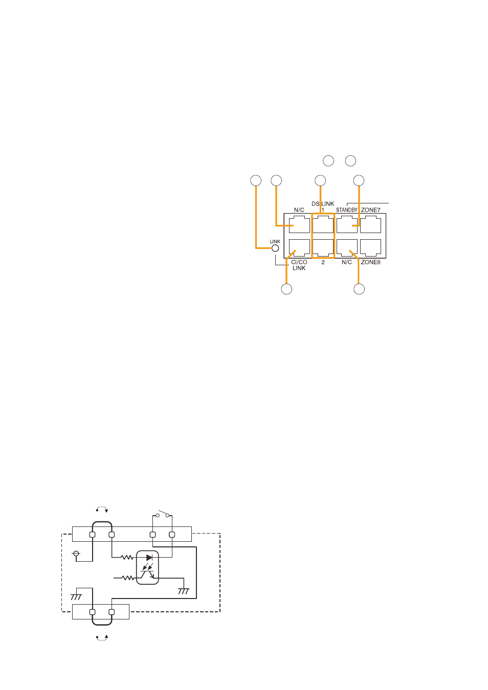
45. CI/CO Link Indicator [LINK] (green)
lights when the SX-2000cI or the SX-2000co is
connected.
46. Unused Terminals [N/C]
these terminals are not used.
47. DS Link Terminals [DS LINK 1/2]
connect either terminal to the DS-Sf link terminal
of the VX-2000DS or DS link IN terminal of the
VX-3000DS.
48. Standby Amplifier Audio Output Terminal
[pA LINK STANDBY]
connect this terminal to the PA lINK terminal of
the VP-200VX Power Amplifier Input Module built
into the VP-2000 series amplifier used for standby
amplifier, or to the PA LINK terminal of the VP-
3000 series amplifier used for standby amplifier.
49. CI/CO Link Terminal [CI/CO LINK]
connect this terminal to the cI/co link Data
terminal of the SX-2000cI or SX-2000co.
50. Audio Output Terminals
[pA LINK ZONE 1 – 8]
connect each terminal to the PA lINK terminal of
the VP-200VX Power Amplifier Input Module built
into the VP-2000 series amplifier used for zone
output, or to the PA lINK terminal of the VP-3000
series amplifier used for zone output.
SX-2100AO
45 46
46
47
48
49
[ Operation of power Feed Jumper and Isolation
Jumper]
VCC
GND
-
+
Power feed jumper
Photo coupler
Internal circuit
Isolation jumper
Control input
[Enlarged view of – on
]
45 49