Operation, Of power feed jumper and isolation jumper" on – Toa SX-2000 Series Installation User Manual
Page 24
24
41. Isolation Jumper 2 [gND]
the supplied removable terminal plug is equipped
with a jumper.
When the jumper is attached, the [–] terminals of
control inputs 3, 4, 7, and 8 are connected to the
internal power supply.
removing the jumper disconnects and isolates
these [–] terminals from this unit. (See "operation
of Power feed Jumper and Isolation Jumper"
shown below.)
42. Control Input Terminals
[CONTROL INpUT 1 – 8]
Photo coupler inputs.
A current of approximately 2 mA flows when
shorted, and the voltage becomes under 40 V Dc
when opened. the input of 100 msec or greater is
required to operate.
these contact inputs can be isolated from the SX-
2000Ao unit by cutting power feed jumpers 1 (43)
and 2 (40) and isolation jumpers 1 (44) and 2 (41).
Each contact input when isolated is 40 V Dc for
maximum applied voltage and approximately
2 mA for the loop current.
Since each terminal is equipped with a current
limiter employing constant current circuitry, there
is no need to limit the current on the external
equipment side.
the [–] terminals of 1, 2, 5, and 6 are common,
while those of 3, 4, 7, and 8 are common.
use the SX-2000 Setting Software to assign
functions to these terminals. (See the separate
Setting Software Instructions, "Event Settings.")
43. power Feed Jumper 1 [vCC]
the supplied removable terminal plug is equipped
with a jumper.
When the jumper is attached, the circuits of
control inputs 1, 2, 5, and 6 are powered from
inside the SX-2000Ao.
removing the jumper disconnects this internal
power supply and thus requires that power be
supplied externally to the circuit. (See "operation
of Power feed Jumper and Isolation Jumper"
shown below.)
44. Isolation Jumper 1 [gND]
the supplied removable terminal plug is equipped
with a jumper.
When the jumper is attached, the [–] terminals of
control inputs 1, 2, 5, and 6 are connected to the
internal power supply.
removing the jumper disconnects and isolates
these [–] terminals from this unit. (See "operation
of Power feed Jumper and Isolation Jumper"
shown below.)
45. Audio Output Terminals [LINE OUTpUT]
output audio signals to be broadcast.
these outputs are electronically balanced, but
can be converted into transformer-balanced
type using optional It-450 transformers. (See
59, "converting an output into a transformer-
)
Note
Each output cannot be converted into unbalanced
type as it is electronically balanced.
to convert each output into unbalanced type, use
an optional It-450 transformer.
46. CI/CO Link Terminal [CI/CO LINK]
connect this terminal to the cI/co link Data
terminal of the SX-2000cI or SX-2000co.
47. CI/CO Link Connection Indicator [LINK]
(green)
lights when the SX-2000cI or the SX-2000co is
connected.
48. Emergency Audio Input Terminal
[EMERgENCY LINE INpUT]
connect a voice evacuation system equipment
to this terminal. the input signal is routed to all
audio output terminals when the SX-2000Ao is
turned off or 24 V Dc is not applied to the 24 V
Emergency cutoff input terminal (49).
49. 24 v Emergency Cutoff Input Terminal
[EMERgENCY CUTOFF DC24 v INpUT]
controls the Emergency audio input.
Input current is under 5 mA.
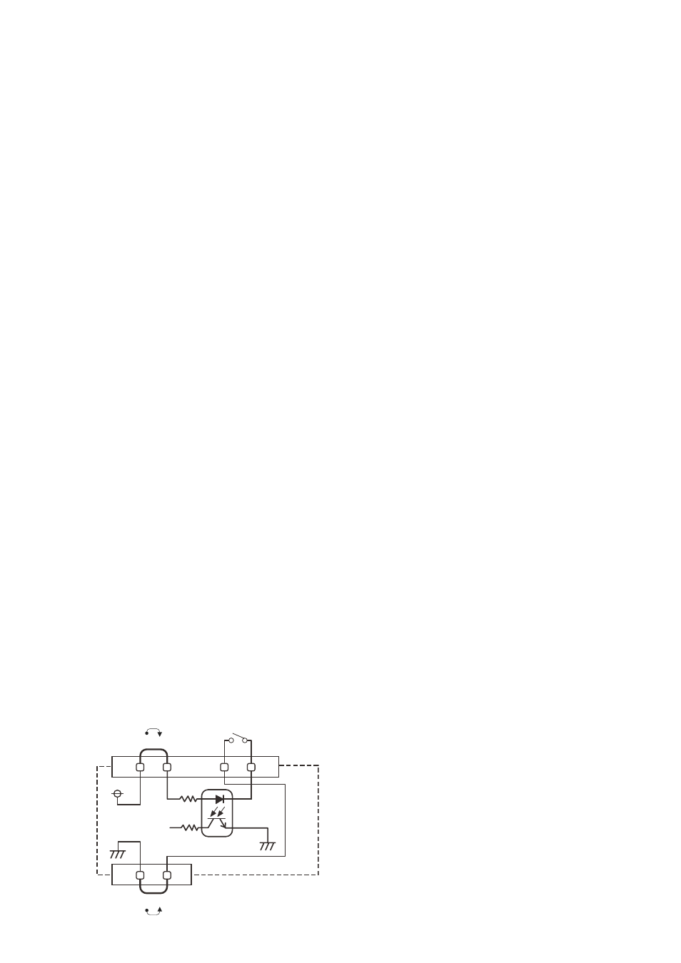
SX-2000AO
[Operation of power Feed Jumper and Isolation Jumper]
VCC
GND
-
+
Power feed jumper
Photo coupler
Internal circuit
Isolation jumper
Control input