Redundant configuration of switching hubs, Redundant configuration of, Switching hubs – Toa SX-2000 Series Installation User Manual
Page 130
130
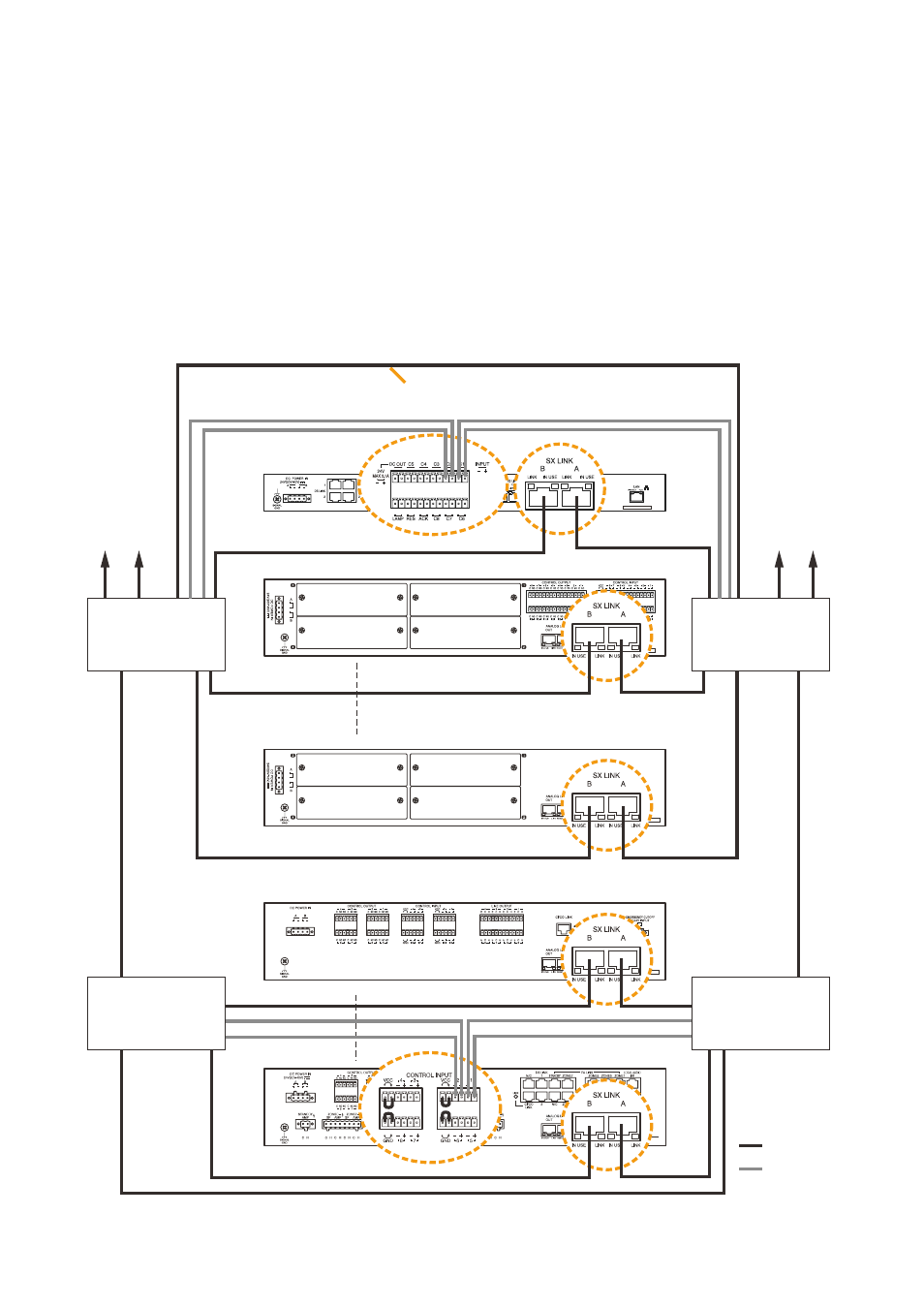
4.5.1. Redundant configuration of switching hubs
In the connection example below, the SX link A and B terminals of each unit are individually connected to
different switching hubs. By using switching hubs with failure status output function, if any one of switching hubs
fails or the main line breaks, such a failure can be detected.
Notes
• Up to 7-level cascade is allowed for switching hub connections.
• After connection completion, reactivate the SX-2000SM, SX-2000AI, SX-2100AI, SX-2000AO, or SX-2100AO
by pressing the reset key on its front panel.
• Perform spanning tree setting within switching hubs. For the setting, contact your network administrator.
• The "External failure input" function needs be assigned to the unit's control input terminal to which the switching
hub's failure status output is connected. (for details, refer to the separate Setting Software Instructions,
"Event Settings.")
SX-2000AI
SX-2000AO
SX-2100AO
SX-2000SM
To other
switching hub
To other
switching hub
Switching hub (B-1)
Switching hub (A-1)
Switching hub (B-2)
Switching hub (A-2)
Main line
Main line
Main line
: SX Link
: Control line
Main line
SX-2100AI
STP Category 5 straight cable
(with RJ45 connectors)
Note: contact your toA dealer for more information on switching hubs.