Toa SX-2000 Series Installation User Manual
Page 60
60
(OPTION)
ATTENTIO
N
CUT SJP181 AND SJP18
2
WHEN MOUNTIN
G
TRANS. T108
T108
SJP181
(OPTION)
ATTENTIO
N
CUT SJP161 AND SJP16
2
WHEN MOUNTIN
G
TRANS. T106
T106
(OPTION)
ATTENTIO
N
CUT SJP121 AND SJP122
WHEN MOUNTIN
G
TRANS. T102
T102
SJP122
SJP121
SJP172
(OPTION)
ATTENTIO
N
CUT SJP171 AND SJP172
WHEN MOUNTIN
G
TRANS. T107
T107
SJP171
(OPTION
)
ATTENTION
CUT SJP141 AND SJP142
WHEN MOUNTIN
G
TRANS. T104
T104
SJP141
SJP152
SJP162
(OPTION
)
ATTENTION
CUT SJP151 AND SJP152
WHEN MOUNTIN
G
TRANS. T105
T105
SJP142
SJP151
SJP182
SJP161
(OPTION)
ATTENTIO
N
CUT SJP111 AND SJP11
2
WHEN MOUNTIN
G
TRANS. T101
T101
SJP112
SJP111
SJP132
(OPTION)
ATTENTIO
N
CUT SJP131 AND SJP132
WHEN MOUNTIN
G
TRANS. T103
T103
SJP131
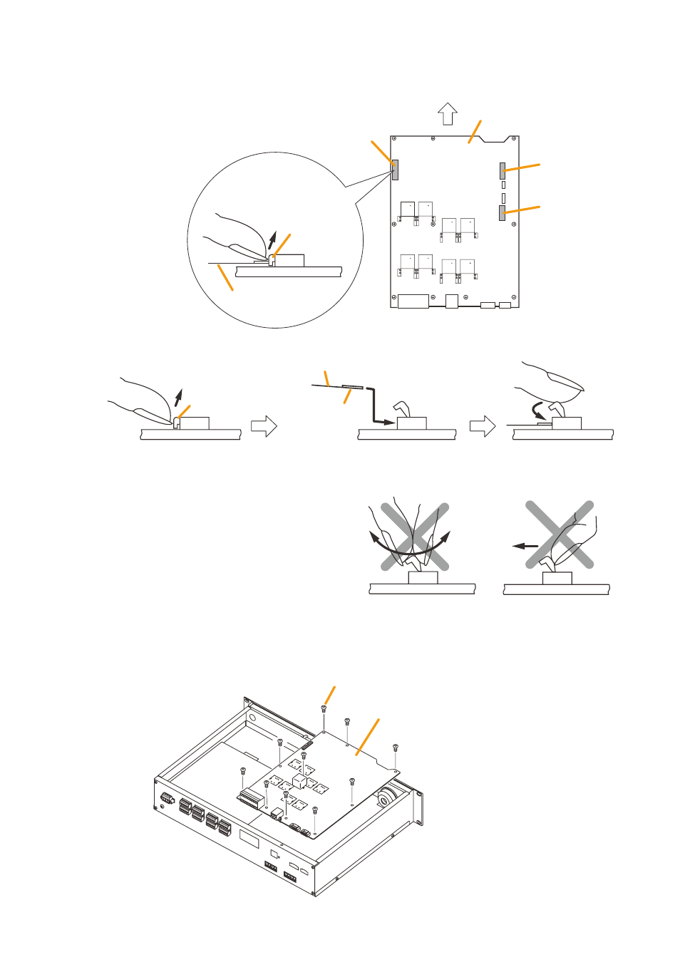
SX-2000AO link circuit board
10P connector
Flat cable connector
Front panel side
11P connector
Flat cable
Side view of the connector
Lock lever
Step 2. Remove the flat cable and connectors (10P and 11P) connected to the link circuit board.
• Detaching a flat cable
to remove the flat cable, first raise the lock lever
on top of the connector.
Raise the lock lever.
Lower the lock lever.
Insert the flat cable with its conductor
surface facing downward.
Flat cable
Lock lever
Conductor surface
Step 3. remove the 10 circuit board mounting screws, then remove the link circuit board.
Link circuit board
Circuit board mounting screw* (10 pieces)
* M3 x 6 binding head machine screw
(with spring washer and plain washer)
• Inserting a flat cable
Note
Pivot the lock lever on its fulcrum to open and
close it.
Avoid gripping the lock lever with the fingers
or twisting it.
Also, do not apply force in the horizontal
direction.
Incorrect usage could damage the lock lever.