Toa SX-2000 Series Installation User Manual
Page 56
56
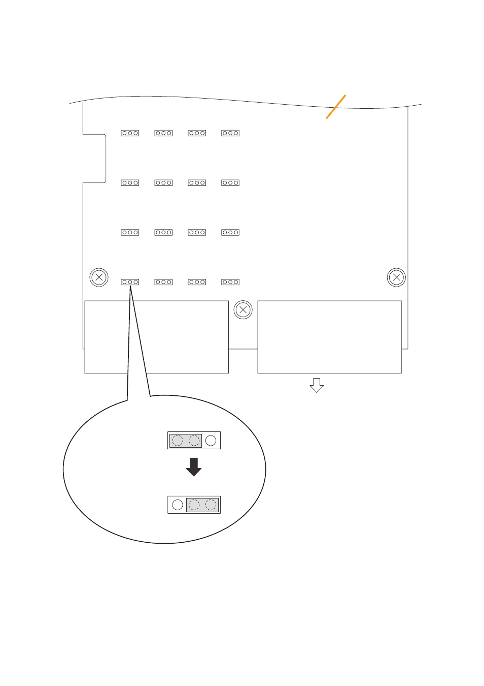
Step 2. change the jumper settings on the cIo circuit board.
Note
This figure shows an example when
the control output 7 is changed into
the normally closed type.
C-OUT
7
NC
7
NO
C-OUT
7
NC
7
NO
Jumper position for the
normally closed output
Jumper position for the
normally open output
(factory-preset)
The numbers at the jumper connectors below correspond to
the control output terminal numbers.
SX-2100AI
CIO circuit board
Rear panel side
16
14
12
10
8
6
4
2
15
13
11
9
7
5
3
1
Step 3. replace the top panel.
Note
In this event, note the specific shapes of the different screws. (See Step 1.)
This manual is related to the following products:
See also other documents in the category Toa Equipment:
- D-2000 Series Installation (84 pages)
- DD-2000 Series Manual (24 pages)
- D-2000 Series Read Me First (12 pages)
- D-2012AS (2 pages)
- D-2012C (4 pages)
- D-901 (96 pages)
- CR-273 (20 pages)
- CR-413-6 (20 pages)
- EV-20R (20 pages)
- MP-1216 (8 pages)
- MB-WT3 (2 pages)
- MT-251H (1 page)
- F-2322C (12 pages)
- F-2852C (12 pages)
- SC-630 (2 pages)
- ES-0851 (4 pages)
- ES-C0651 (4 pages)
- F-1000B (18 pages)
- F-122C (12 pages)
- F-122CU (20 pages)
- F-122CU2 (16 pages)
- F-1300B (18 pages)
- F-1522SC (8 pages)
- AN-9001 (1 page)
- C-AL80 (16 pages)
- DP-K1 (102 pages)
- DP-K1 (28 pages)
- DP-L2 v.2.00 (28 pages)
- DP-SP3 Protocol (14 pages)
- DP-SP3 (24 pages)
- DP-SP3 (75 pages)
- E-232 (8 pages)
- AT-063AP (4 pages)
- BS-1015BSB (8 pages)
- BS-1030B (4 pages)
- BS-634 (4 pages)
- BS-1034EN (8 pages)
- BS-1110W (4 pages)
- BS-301B (8 pages)
- BS-301B AS (4 pages)
- MB-WT1 (1 page)
- S-D7300 (16 pages)
- VX-200SP-2 (24 pages)
- YA-1000A (1 page)
- ZM-9001 (2 pages)