Rear – Toa SX-2000 Series Installation User Manual
Page 8
8
21
22
23
24 25 26 27
28 29 30
31 32
20
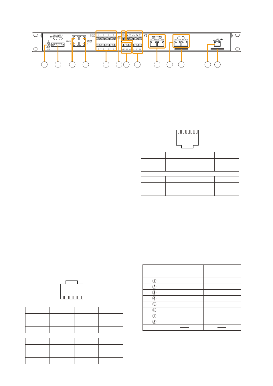
[Rear]
Shield
Orange/White
Orange
Green/White
Blue
Blue/White
Green
Brown/White
Brown
Green/White
Green
Orange/White
Blue
Blue/White
Orange
Brown/White
Brown
RJ45's
pin No.
Cable color
Cable color
(T568B type)
(T568A type)
SX-2000SM
20. Functional Earth Terminal [SIgNAL gND]
Hum noise may be generated when external
equipment is connected to the unit. connecting
this terminal to the functional earth terminal of the
external equipment may reduce the hum noise.
Note: this terminal is not for protective earth.
21. DC power Input Terminal [DC pOwER IN]
connect an optional Dc power supply unit to
this terminal. Select the Dc power supply source
with consideration given to the current power
consumption of the system the SX-2000Sm is
to be connected to. When not using a redundant
power system*, connect the [+] terminal of input A
to the [+] terminal of input B, and the [–] terminal
of input A to the [–] terminal of input B. (refer
to the Instruction manual attached to the VX-
2000DS/3000DS.)
*
A method of connecting separate power
sources to each power input or connecting the
commercial power supply and backup power
supply separately to each power input to prevent
the system from going down when a cable is
broken or power fails.
22. DS Link Terminals [DS LINK]
connect either terminal to the DS-Sf link terminal
of the VX-2000DS or DS link IN terminal of the
VX-3000DS.
23. Status Output Terminals [STATUS OUTpUT]
relay make contact outputs. Each contact
capacity is rated at 40 V Dc for withstand voltage,
and 2 mA – 300 mA for control current. the
number of outputs is 4. the rJ45 connector's pin
arrangement is as follows:
[Upper row]
• CpU FAULT
cPu irregularity in progress:
Pin 1 – Pin 2 shorted
Normal: Pin 1 – Pin 3 shorted
• gENERAL FAULT
Some irregularity in progress:
Pin 5 – Pin 7 shorted
Normal: Pin 5 – Pin 8 shorted
[Lower row]
• BUZZER
Buzzer oN: Pin 1 – Pin 2 shorted
Buzzer off: Pin 1 – Pin 3 shorted
• CpU OFF
remote microphone-initiated general urgency
all-call broadcasts in progress:
Pin 5 – Pin 7 shorted.
General urgency all-call broadcasts not initiated:
Pin 5 – Pin 8 shorted.
[RJ45 connector's pin No. vs. Cable color]
24. Control Output Terminals [OUTpUT C1 – C8]
relay make contact outputs. Each contact
capacity is rated at 40 V Dc for withstand voltage,
and 2 mA – 300 mA for control current.
these terminals are controlled by the SX-2000
1
1
2
3
4
5
6
7
8
Pin 4
Pin 3
Pin 2
Pin 1
Not used
cPu
cPu
cPu
fAult
fAult
fAult
Nc
No
com
Pin 8
Pin 7
Pin 6
Pin 5
GENErAl GENErAl
Not used
GENErAl
fAult
fAult
fAult
Nc
Nc
com
2
8
7
6
5
4
3
2
1
Pin 5
Pin 6
Pin 7
Pin 8
cPu off
Not used
cPu off
cPu off
com
No
Nc
Pin 1
Pin 2
Pin 3
Pin 4
BuZZEr
BuZZEr
BuZZEr
Not used
com
No
Nc