Toa SX-2000 Series Installation User Manual
Page 29
29
50
51
52
53 54 55
56 57
58
59
38
39
40 44
45 49
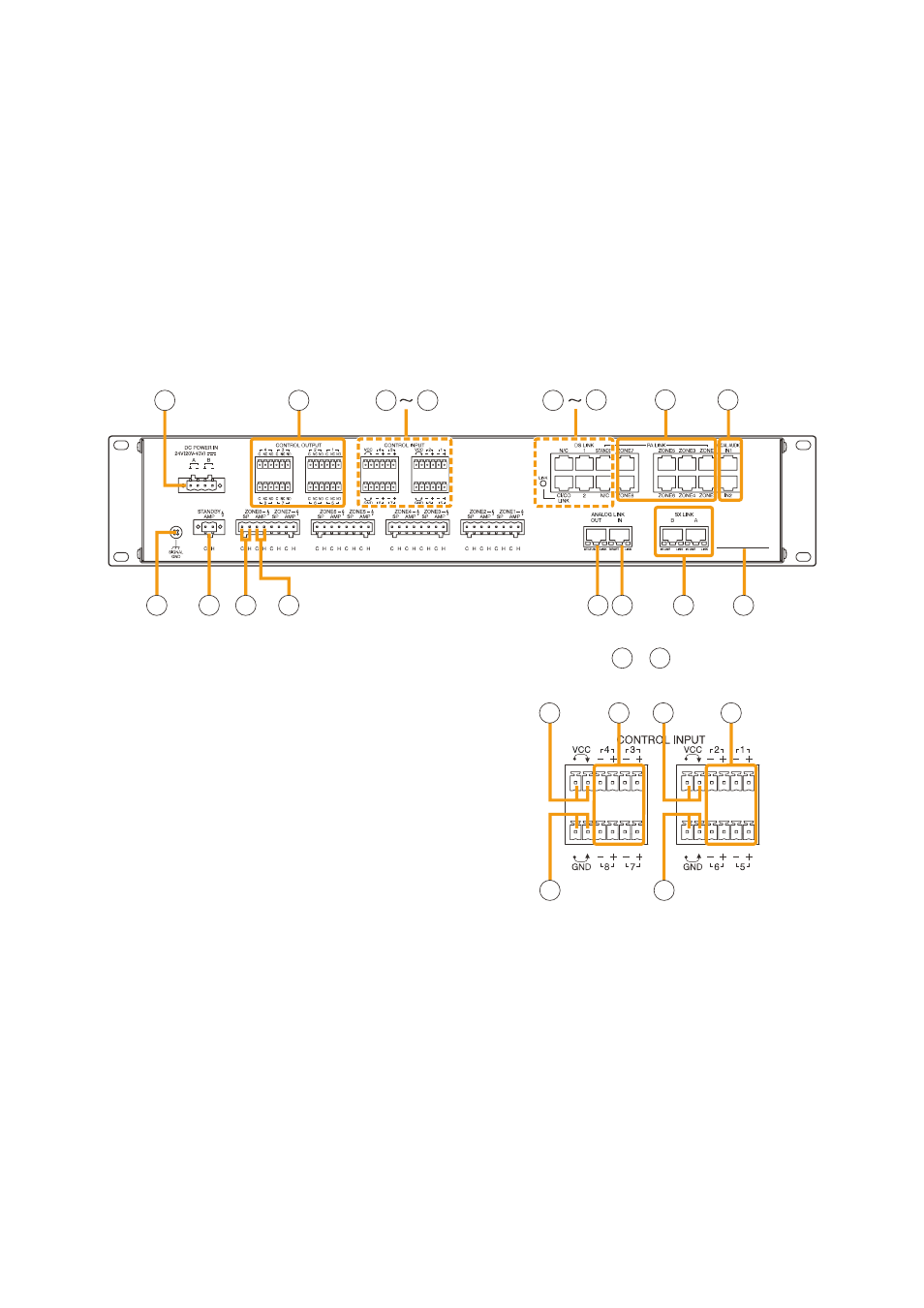
38. DC power Input Terminal [DC pOwER IN]
connect an optional Dc power supply unit to
this terminal. Select the Dc power supply source
with consideration given to the current power
consumption of the system the SX-2100Ao is to
be connected to. When not using a redundant
power system*, connect the [+] terminal of input A
to the [+] terminal of input B, and the [–] terminal
of input A to the [–] terminal of input B.
(refer to the Instruction manual attached to the
VX-2000DS/3000DS.)
*
A method of connecting separate power
sources to each power input or connecting the
commercial power supply and backup power
supply separately to each power input to prevent
the system from going down when a cable is
broken or power fails.
39. Control Output Terminals
[CONTROL OUTpUT 1 – 8]
relay make contact outputs. Each contact
capacity is rated at 40 V Dc for withstand voltage,
and 2 mA – 300 mA for control current. these
terminals are controlled by the SX-2000 Setting
Software. (See the separate Setting Software
Instructions, "Pattern Settings.")
Note
With this Setting Software, these control terminals
can also be set to control external attenuators.
(See the Setting Software Instructions, "System
Settings.")
40. power Feed Jumper 2 [vCC]
the supplied removable terminal plug is equipped
with a jumper.
When the jumper is attached, the circuits of
control inputs 3, 4, 7, and 8 are powered from
inside the SX-2100Ao.
removing the jumper disconnects this internal
power supply and thus requires that power be
supplied externally to the circuit. (See
of Power feed Jumper and Isolation Jumper" on
SX-2100AO
40
40
41
41
[Enlarged view of – above]
42
43
44
44
32. Local Audio Input Level Meter
Indicates each level of signals applied to the local
audio inputs 1 and 2 while the local audio control
inputs 1 and 2 are activated, respectively.
33. Control Output Unit Connection Indicator [2]
Indicates "2" when the SX-2000co is connected
to the SX-2100Ao.
34. Control Input Unit Connection Indicator [1]
Indicates "1" when the SX-2000cI is connected to
the SX-2100Ao.
35. Monitor Level Meter
Indicates the sound volume level of the output
channel being monitored.
36. Monitor Level Meter Scale
lights when the monitor oN/off key (15) is set
to oN.
37. Monitor ON/OFF Indicator [LEvEL]
lights when the monitor oN/off key (15) is set
to oN.
[Rear]