Operation of power feed jumper and isolation, Operation of power feed jumper – Toa SX-2000 Series Installation User Manual
Page 19
19
46. Control Input Terminals
[CONTROL INpUT 1 – 16]
Photo coupler inputs. A current of approximately
2 mA flows when shorted, and the voltage
becomes under 40 V Dc when opened.
the input of 100 msec or greater is required to
operate. these contact inputs can be isolated
from the SX-2100AI unit by cutting the power
feed jumper (45) and the isolation jumper (44).
Each contact input when isolated is 40 V Dc
for maximum applied voltage and approximately
2 mA for the loop current. Since each terminal
is equipped with a current limiter employing
constant current circuitry, there is no need to limit
current on the external equipment side. the [–]
terminals of all control inputs are common. use
the SX-2000 Setting Software to assign functions
to these terminals. (See the separate Setting
Software Instructions, "Event Settings.")
47. Analog Link Output Terminal
[ANALOg LINK OUT]
connect this terminal to the analog link input
terminal of the SX-2000AI, SX-2100AI, SX-
2000Ao, or SX-2100Ao.
48. Analog Link Input Terminal
[ANALOg LINK IN]
connect this terminal to the analog link output
terminal of the SX-2000Sm, SX-2000AI, SX-
2100AI, SX-2000Ao, or SX-2100Ao.
49. SX Link Terminals [SX LINK A/B]
use switching hubs to connect between the SX
link terminals of the SX-2000Sm, SX-2000AI, SX-
2100AI, SX-2000Ao, and SX-2100Ao. connect
each of the SX links A and B to the same
switching hub*, or to different switching hubs* that
have been connected in star configuration.
Notes
• Be sure to connect both terminals of A and B.
• After connection completion, press the Reset
key to reactivate the SX-2100AI.
* contact your toA dealer for more information
on switching hubs.
50. MAC Address
mAc address to be used for SX link connection.
1
2
Function
LED On
LED Off
1. Not used
2. OUT connection confirmation Connected Unconnected
3
4
Function
LED On
LED Off
4. Not used
3. RESET input
Resetting
Normal
SX-2100AI
1
2
3
4
Function
LED On/Flashing
LED Off
2. B connection confirmation
Connected
Unconnected
1. B operation in progress
indication
Operating
Not operating
4. A connection confirmation
Connected
Unconnected
3. A operation in progress
indication
Operating
Not operating
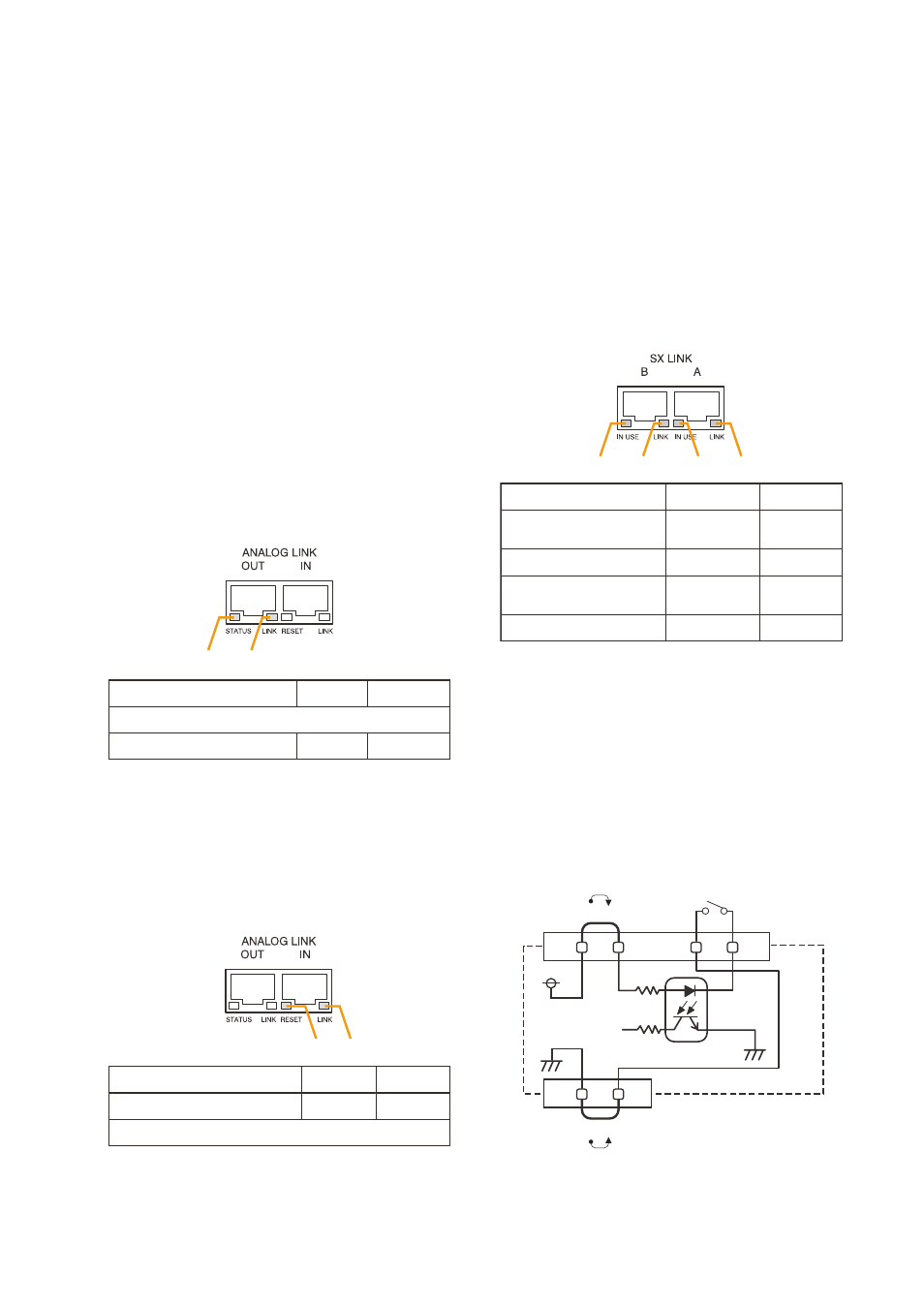
[ Operation of power Feed Jumper and
Isolation Jumper]
VCC
GND
-
+
Power feed jumper
Photo coupler
Internal circuit
Isolation jumper
Control input