P. 109 – Toa SX-2000 Series Installation User Manual
Page 109
109
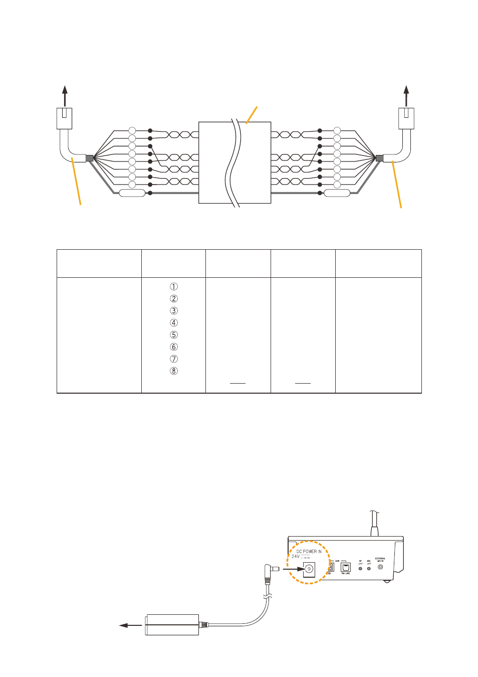
• When using a shielded CPEV cable but not the RM-200RJ, connect the cable to STP Category 5 straight
cable (with rJ45 connectors) as follows.
Pair 1 with 2, 3 with 6, 4 with 5, and 7 with 8.
Monitor in (H)
Monitor in (C)
RM data
Audio out (H)
Audio out (C)
RM data
DC power in (+)
DC power in (-)
Shield
Shield
Orange/White
Orange
Green/White
Blue
Blue/White
Green
Brown/White
Brown
Green/White
Green
Orange/White
Blue
Blue/White
Orange
Brown/White
Brown
Monitor out (H)
Monitor out (C)
RM data
Audio in (H)
Audio in (C)
RM data
DC power out (+)
DC power out (-)
Shield
RM-200SA
RJ45 connector
pin No.
Cable color
(T568B type)
Cable color
(T568A type)
SX-200RM
Over 4-pair shielded
CPEV cable (main cable)
STP Category 5 straight cable
(with an RJ45 connector)
STP Category 5 straight cable
(with an RJ45 connector)
RJ45 connector
pin No.
RJ45 connector
pin No.
To SX-200RM
To RM-200SA
1
2
5
6
3
4
7
8
Shield
1
2
5
6
3
4
7
8
Shield
[when supplying power from the AC adapter]
When supplying power to the rm-200SA from the optional AD-246 Ac Adapter using the cables listed in the
tables on
, the maximum length of connection cable (main line) is 800 m regardless of the type of cable
and the number of remote microphone expansion units.
Note
to power the remote microphones even during power failures, a battery backup is also needed for the Ac
adapter.
RM-200SA rear
AD-246 (optional)
To AC power