Rm-200sf, rm-200sa, and rm-210, Rm-200sf and rm-200sa device number settings, Dip switches 1 – 3 operation) – Toa SX-2000 Series Installation User Manual
Page 66: P. 66
66
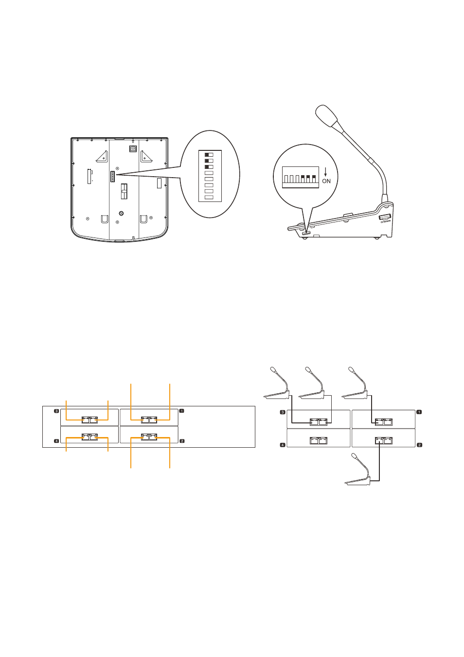
2.5. RM-200SF, RM-200SA, and RM-210
2.5.1. RM-200SF and RM-200SA device number settings (DIp switches 1 – 3 operation)
Set device numbers (ID numbers) using DIP switches 1 – 3 located on the bottom panel of the rm-200Sf and
the side panel of the rm-200SA.
8
7
6
5
4
3
2
1
TERMINATION
CPU OFF
LEVEL METER
COMMUNICATION
UNIT ID
On
Off
DIP SWITCH
1
2
3
4
5
6
RM-200SF bottom
RM-200SA side
1
2
ON
3
4
5
6
7
8
SX-2000AI/2100AI
1 2
1 2
1 2
1 2
1 2
1 2
1 2
1 2
[Channel number and device number of SX-2000AI/2100AI]
[Setting example]
Device No. 1
Device No. 3
Device No. 5 Device No. 6
CH 5
(Device No. 5)
CH 6
(Device No. 6)
CH 7
(Device No. 7)
CH 8
(Device No. 8)
CH 1
(Device No. 1)
CH 2
(Device No. 2)
CH 3
(Device No. 3)
CH 4
(Device No. 4)
Note
connect one rm-200Sf or rm-200SA to each input of SX-200rm mounted in the SX-2000AI or SX-2100AI.
the input channels to which the rm-200Sf and rm-200SA can be connected must have been assigned using
the SX-2000 Setting Software, and each connected rm-200Sf's and rm-200SA's device number must match
the input channel number of the SX-2000AI or SX-2100AI to which it is connected.