Rear – Toa SX-2000 Series Installation User Manual
Page 35
35
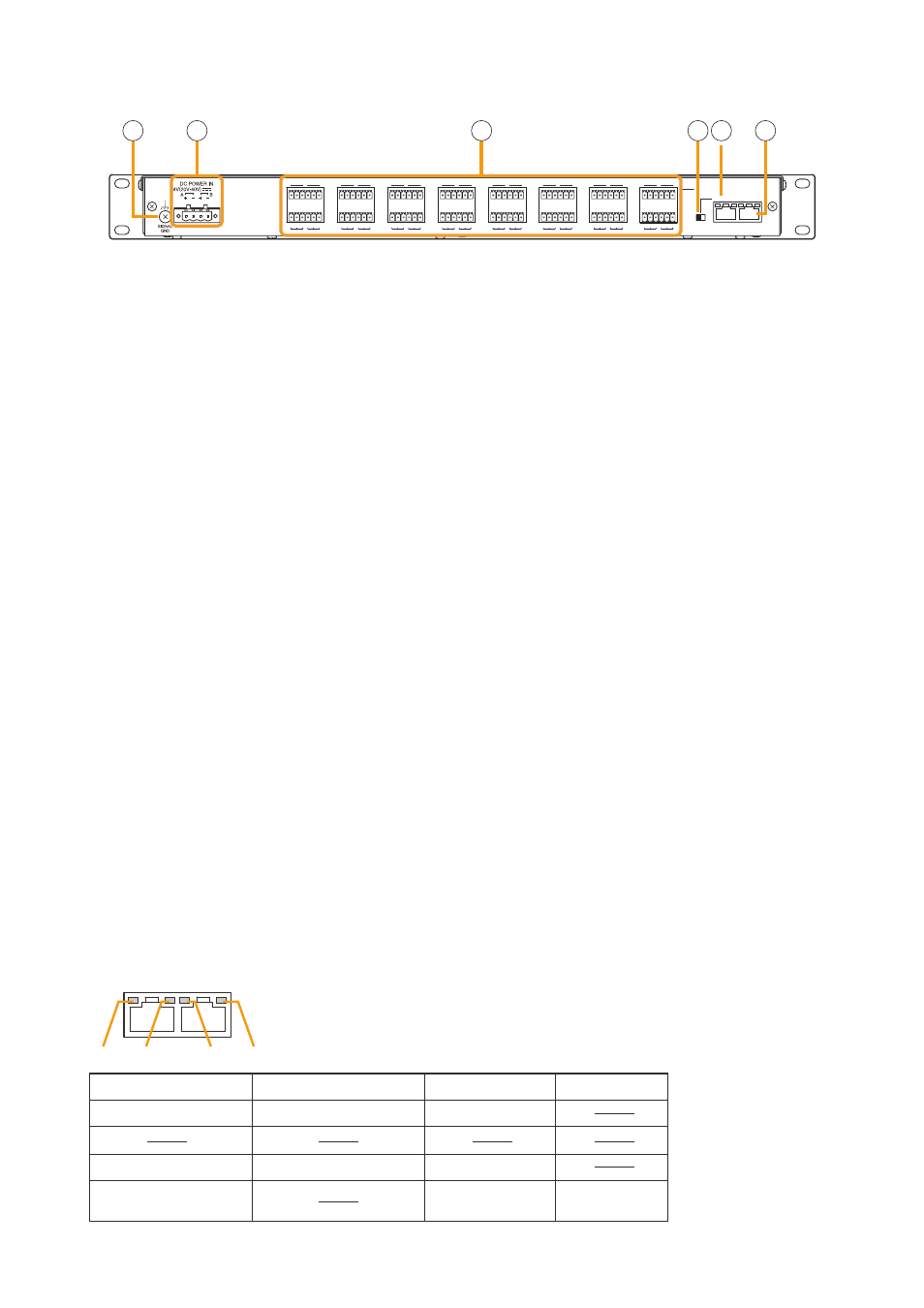
[Rear]
CI/CO LINK
THROUGH DATA
ON
OFF
1
2
3
4
5
6
7
8
17
18
19
20
21
22
23
24
9
10
11
12
13
14
15
16
25
26
27
28
29
30
31
32
CONTROL
OUTPUT
C NC NO
10
11
14 15
13
12
10. Functional Earth Terminal [SIgNAL gND]
Hum noise may be generated when external
equipment is connected to the unit.
connecting this terminal to the functional earth
terminal of the external equipment may reduce
the hum noise.
Note
this terminal is not for protective earth.
11. DC power Input Terminal [DC pOwER IN]
connect an optional Dc power supply unit to this
terminal.
Select the Dc power supply source with
consideration given to the current power
consumption of the system the SX-2000co is
to be connected to. When not using a redundant
power system*, connect the [+] terminal of input A
to the [+] terminal of input B, and the [–] terminal
of input A to the [–] terminal of input B. (refer
to the Instruction manual attached to the VX-
2000DS/3000DS.)
*
A method of connecting separate power
sources to each power input or connecting the
commercial power supply and backup power
supply separately to each power input to prevent
the system from going down when a cable is
broken or power fails.
12. Control Output Terminals
[CONTROL OUTpUT 1 – 32]
relay make contact outputs. Each contact
capacity is rated at 40 V Dc for withstand voltage,
and 2 mA – 300 mA for control current. these
terminals are controlled by the SX-2000 Setting
Software. (See the separate Setting Software
Instructions, "Pattern Settings.")
13. CI/CO Link Through Switch [ON/OFF]
Set to oN when using the cI/co link through
terminal (14). (factory-preset: off)
14. CI/CO Link Through Terminal
[CI/CO LINK ThROUgh]
connect this terminal to the cI/co link Data
terminal of the SX-2000cI.
refer to the table below for the indicators'
functions and status.
15. CI/CO Link Data Terminal [CI/CO LINK DATA]
connect this terminal to the cI/co link terminal
of the SX-2000Ao or SX-2100Ao, or cI/co link
through terminal of the SX-2000cI.
refer to the table below for the indicators'
functions and status.
SX-2000CO
CI/CO LINK
THROUGH DATA
Functions
LED On or Flashing (green)
LED Off
LED On (orange)
1. CI/CO LINK status
Communication start
Communication stop
2.
3. CI/CO LINK status
Communication start
Communication stop
4. CI/CO LINK connection
confirmation
Unconnected
Connected
1
2
3
4
[Indicators' functions and status of the CI/CO Link Through/Data terminals]