Screen display (common) – Toa SX-2000 Series Installation User Manual
Page 143
143
Step 9. Set the DIP switch 8 to off.
Step 10. replace the protective cover.
ON
1 2 3 4 5 6 7 8
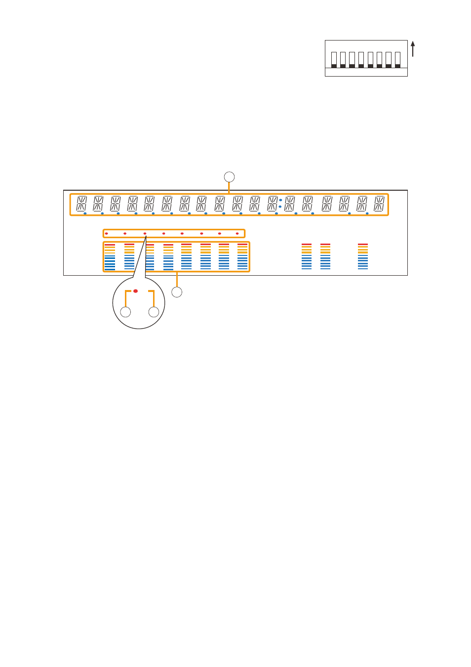
5.3.2. Screen display (Common)
Shown below is the fluorescent display while in the impedance initialization setting mode.
COM
FAULT
KEYLOCK
EMERGENCY
OL
0
–10
–20
–30
–40
OL
0
–10
–20
–30
–40
FADER
LEVEL
LEVEL
1
2
3
4
5
6
7
8
1
2
1
4
3
3
2
3
1. Text Display Area
Displays the menu screen and information.
2. Channel Selection Indicator
lights when the corresponding output channel is
selected.
3. Channel Number Indicator
Indicates the channel number.
All channel numbers (1 – 8) remain lit while in this
setting mode.
4. Level Meter
light-up position of lED indicates the initial
impedance value (reference value) and degree of
oPEN or SHort of the selected channel, at which
the indicator (2) is illuminated.
All the lEDs go off if the "clEAr INItIAl ImP."
(Setting clear) is selected.