Maxim Integrated MAXQ610 User Manual
Maxq610 user’s guide
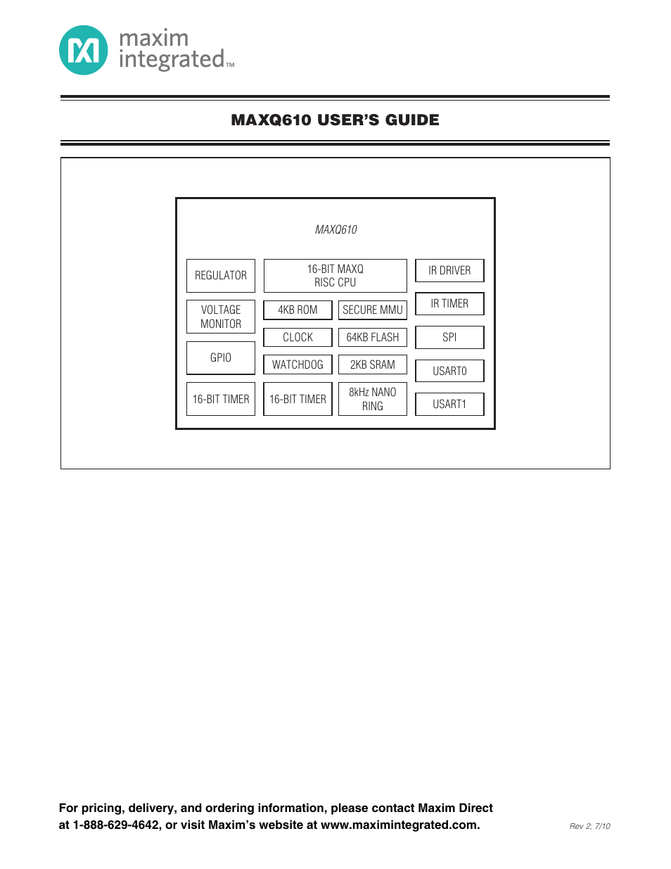
Table of contents
Document Outline
- TABLE OF CONTENTS
- SECTION 1: Overview
- SECTION 2: Architecture
- 2.1 Instruction Decoding
- 2.2 Register Space
- 2.3 Memory Organization
- 2.4 Memory Management Unit
- 2.5 Memory Mapping
- 2.6 Memory Protection
- 2.6.1 Rules for System Software
- 2.6.2 Privilege Exception Interrupt
- 2.6.3 Memory Access Protection Impact on Data Pointers (and Code Pointer)
- 2.6.4 Debugging
- 2.6.5 Enabling Memory Protection
- 2.6.6 Reset Procedure and Setup of Memory Protection
- 2.6.7 Loader Access Control
- 2.6.8 Disabling MAXQ610-Specific Memory Access Features
- 2.6.9 No User-Loader Segment
- 2.7 Clock Generation
- 2.8 Wake-Up Timer
- 2.9 Interrupts
- 2.10 Operating Modes
- 2.11 Reset Mode
- 2.12 Power-Management Mode
- 2.13 Stop Mode
- SECTION 3: Programming
- 3.1 Addressing Modes
- 3.2 Prefix Operations
- 3.3 Reading and Writing Registers
- 3.3.1 Loading an 8-Bit Register with an Immediate Value
- 3.3.2 Loading a 16-Bit Register with a 16-Bit Immediate Value
- 3.3.3 Moving Values Between Registers of the Same Size
- 3.3.4 Moving Values Between Registers of Different Sizes
- 3.3.5 8-Bit Destination ← Low Byte (16-Bit Source)
- 3.3.6 8-Bit Destination ← High Byte (16-Bit Source)
- 3.3.7 16-Bit Destination ← Concatenation (8-Bit Source, 8-Bit Source)
- 3.3.8 Low (16-Bit Destination) ← 8-Bit Source
- 3.3.9 High (16-Bit Destination) ← 8-Bit Source
- 3.4 Reading and Writing Register Bits
- 3.5 Using the Arithmetic and Logic Unit
- 3.5.1 Selecting the Active Accumulator
- 3.5.2 Enabling Autoincrement and Autodecrement
- 3.5.3 ALU Operations Using the Active Accumulator and a Source
- 3.5.4 ALU Operations Using Only the Active Accumulator
- 3.5.5 ALU Bit Operations Using Only the Active Accumulator
- 3.5.6 Example: Adding Two 4-Byte Numbers Using Autoincrement
- 3.6 Processor Status Flag Operations
- 3.7 Controlling Program Flow
- 3.8 Accessing the Stack
- 3.9 Accessing Data Memory
- 3.10 Using the Watchdog Timer
- SECTION 4: System Register Description
- SECTION 5: Peripheral Register Modules
- SECTION 6: General-Purpose I/O Module
- SECTION 7: Timer/Counter Type B
- SECTION 8: IR Timer
- SECTION 9: Serial I/O Module
- SECTION 10: Serial Peripheral Interface (SPI) Module
- SECTION 11: Test Access Port (TAP)
- SECTION 12: In-Circuit Debug Mode
- SECTION 13: In-System Programming (JTAG)
- SECTION 14: MAXQ610 Instruction Set Summary
- SECTION 15: Utility ROM
- REVISION HISTORY