1 background mode operation, 12 .1 background mode operation -3, Maxq610 user’s guide – Maxim Integrated MAXQ610 User Manual
Page 154
12-3
MAXQ610 User’s Guide
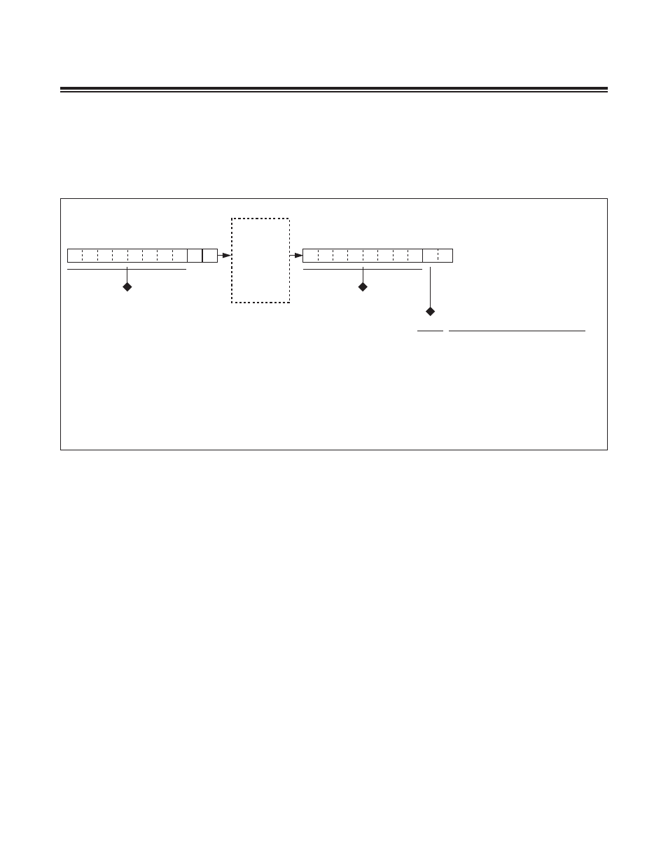
The host now can transmit and receive serial data through the 10-bit data shift register that exists between the TDI
input and TDO output during DR-scan sequences . All background and debug mode communication (commands, data
input/output, and status) occurs through this serial channel . Each 10-bit exchange of data between the host and the
MAXQ610 internal hardware is composed of two status bits and a single byte of command or data .
The 10-bit word is always transmitted least significant bit first with the format shown below .
The data byte portion of the 10-bit shift register is interfaced directly to the ICDB parallel register . The ICDB register
functions as the holding data register for both transmit and receive operations . On the falling edge of TCK in the
update-DR state, the outgoing data is loaded from the ICDB parallel register to the debug shift register and the incom-
ing shift register data is latched in the ICDB parallel register .
12.1 Background Mode Operation
When the instruction register is loaded with the debug instruction (IR[2:0] = 010b), the host can communicate with the
MAXQ610 microcontroller in a background mode using TAP DR-scan sequences without disturbing CPU operation .
Note, however, that JTAG in-system programming also requires use of the 10-bit debug shift register and, if enabled
(SPE, PSS[1:0] = 100b), takes precedence over background mode communication . When operating in background
mode, the status bits are always cleared to 00b (nondebug), which indicates that the MAXQ610 microcontroller is
ready to receive background mode commands .
The host can perform the following operations from background mode:
• Read/write internal breakpoint registers (BP0 to BP5)
• Read/write internal in-circuit debug registers (ICDC, ICDF, ICDA, ICDD)
• Monitor to determine when a breakpoint match has occurred
• Directly invoke debug mode
The background mode commands supported by the MAXQ610 microcontroller are shown in Table 12-1 . Encodings
not listed in this table are not supported in background mode and are treated as no operations .
TDI
TDO
MAXQ610
x
x
0
9
0
9
HOST COMMAND/DATA INPUT
MAXQ610 DATA OUTPUT
s[1:0]
00
NONDEBUG. DEFAULT CONDITION,
BACKGROUND MODE, OR DEBUG ENGINE
INACTIVE.
01
DEBUG IDLE. DEBUG ENGINE IS READY TO
RECEIVE DATA FROM THE HOST (COMMAND, DATA).
10
DEBUG BUSY. DEBUG ENGINE IS BUSY WITHOUT
VALID DATA (i.e., ROM CODE EXECUTION, TRADE
OPERATIONS).
11
DEBUG VALID. DEBUG ENGINE IS BUSY WITH
VALID DATA.
STATUS CONDITION