4 ir receive, 8 .4 ir receive -5, Maxq610 user’s guide – Maxim Integrated MAXQ610 User Manual
Page 118
8-5
MAXQ610 User’s Guide
8.4 IR Receive
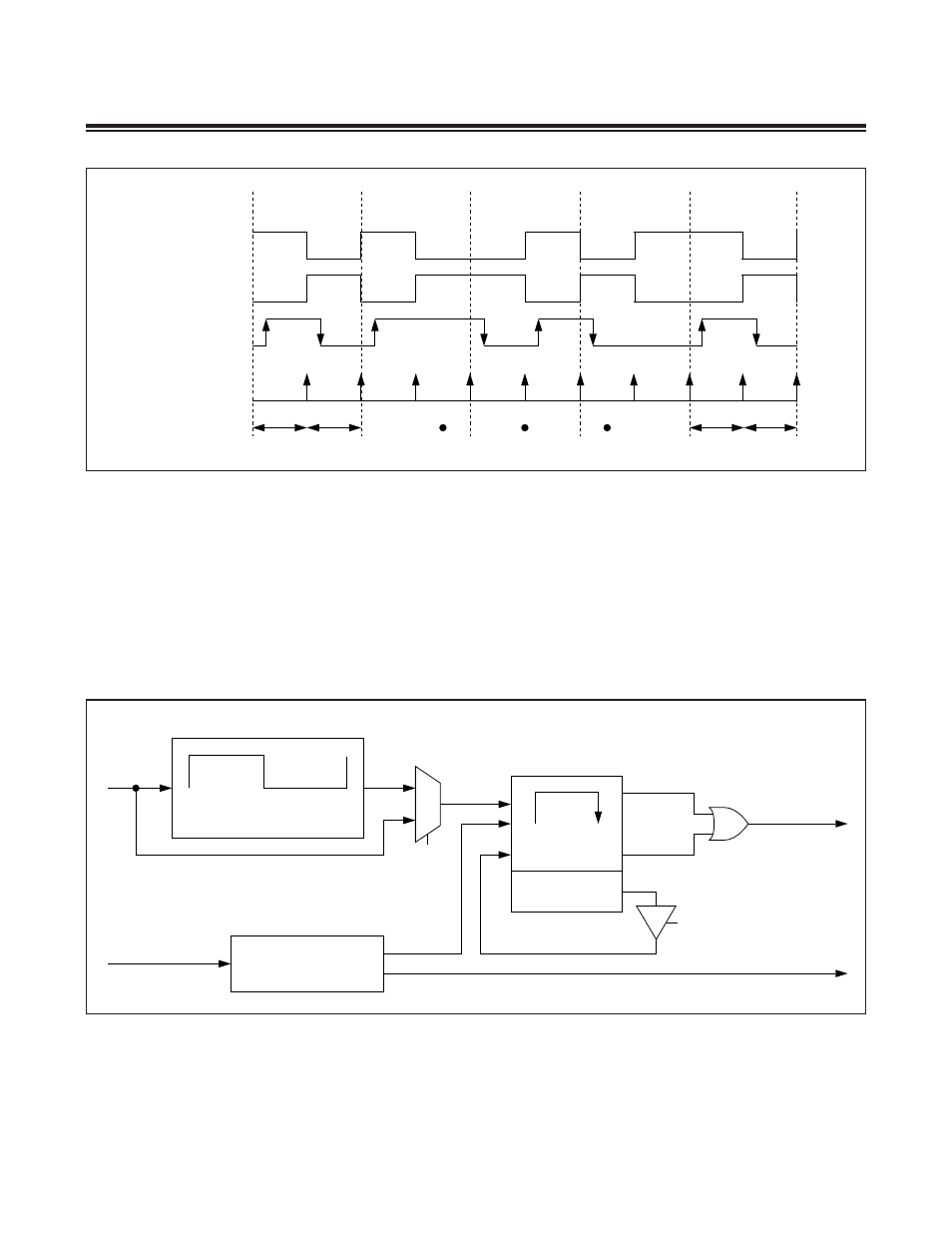
When configured in receive mode (IRMODE = 0), the IR hardware supports the IRRX capture function . The IRRXSEL[1:0]
bits define which edge(s) of the IRRX pin should trigger IR timer capture function .
The IR module starts operating in the receive mode when IRMODE = 0 and IREN = 1 . Once started, the IR timer (IRV)
starts up counting from 0000h when a qualified capture event as defined by IRRXSEL happens . The IRV register will,
by default, be counting carrier cycles as defined by the IRCA register . However, the IR clock frequency mux enable
(IRCFME) bit can be set to 1 to allow clocking of the IRV register directly with the IRCLK for finer resolution . When
IRCFME = 0, the IRCA-defined carrier is counted by IRV . When IRCFME = 1, the IRCLK clocks the IRV register .
Figure 8-4. External IRTXM (Modulator) Output
Figure 8-5. IR Capture
0
0
0
0
1
1
1
1
IRDATA
IRMT
IRMT
IRMT
IRMT
IR INTERRUPT
IRV INTERVAL
IRTXM
(IRTXPOL = 1)
IRTXM
(IRTXPOL = 0)
0
1
IRCAH + 1
IRCFME
RESER IRV TO 0000h
IRXRL
IRCAL + 1
CARRIER GENERATION
EDGE DETECT
CARRIER MODULATION
IR TIMER OVERFLOW
IR INTERRUPT
INTERRUPT TO CPU
IRDATA
COPY IRV TO IRMT
ON EDGE DETECT
0000h
IRV
IRCLK
IRRX PIN