2 baud-rate generation, 1 mode 0 baud rate, 2 mode 2 baud rate – Maxim Integrated MAXQ610 User Manual
Page 133: 3 mode 1 or 3 baud rate, 4 baud-clock generator, 9 .2 baud-rate generation -8, Table 9-2 . usart baud-clock summary -8, Maxq610 user’s guide, Table 9-2. usart baud-clock summary
9-8
MAXQ610 User’s Guide
9.2 Baud-Rate Generation
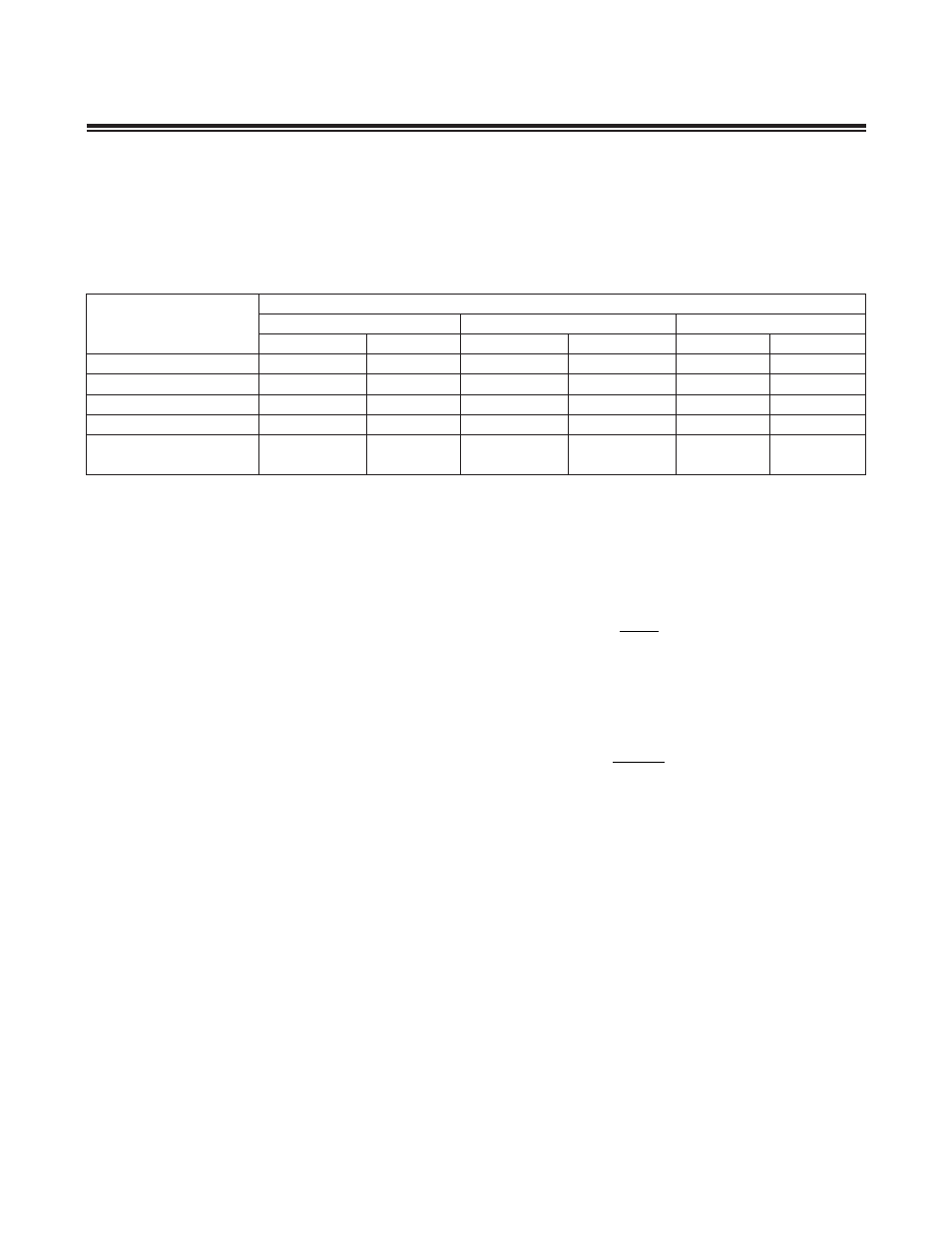
Each mode of operation has a baud-rate generator associated with it . The baud-rate generation techniques are impact-
ed by certain user options such as the power-management mode enable (PMME), serial mode 2 (SM2) select bit, and
baud-rate doubler (SMOD) bit . Table 9-2 summarizes the effects of the various user options on the USART baud clock .
9.2.1 Mode 0 Baud Rate
Baud rates for mode 0 are driven directly from the system clock source divided by either 12 or 4, with the default case
being divided by 12 . The user can select the shift clock frequency using the SM2 bit in the SCON register . When SM2
is set to 0, the baud rate is fixed at a divide by 12 of the system clock . When SM2 is set to 1, the baud rate is fixed at
a divide by 4 of the system clock .
Mode 0 Baud Rate = System Clock Frequency x
SM2
3
12
9.2.2 Mode 2 Baud Rate
In this asynchronous mode, baud rates are also generated from the system clock source . The user can effectively
double the USART baud clock frequency by setting the SMOD bit to 1 . The SMOD bit is set to 0 on all resets, thus
making divide by 64 the default setting . The baud rate is given by the following formula:
Mode 2 Baud Rate = System Clock Frequency x
SMOD
2
64
9.2.3 Mode 1 or 3 Baud Rate
These asynchronous modes are commonly used for communication with PCs, modems, and other similar interfaces .
The baud rates are programmable using the baud-clock generator in the USART module . The baud-clock generator
is basically a phase accumulator that generates a baud clock as the result of phase overflow into the most significant
bit of the phase shifter . This baud-clock generator is driven by the system clock or system clock divided-by-4 source
(depending upon the state of the SMOD bit) . The baud-clock generator output is always divided by 16 to generate the
exact baud rate .
9.2.4 Baud-Clock Generator
The baud-clock generator is essentially a phase accumulator that produces a baud clock as the result of phase over-
flow from the most significant bit of the phase shift circuitry . A 16-bit phase register (PR) is programmable by the user
to select a suitable phase value for its baud clock . The phase value dictates the phase period of the accumulation
process . The phase value is added to the current phase accumulator value on each system clock (SMOD = 1) or every
fourth system clock (SMOD = 0) . The baud clock is the result of addition overflow out of the most significant bit of the
phase accumulator (bit 16) . The baud-clock generator output is always divided by 16 to produce the exact baud rate .
Table 9-2. USART Baud-Clock Summary
*The BAUD frequency is determined by the baud-clock generator (described later in this section).
SYSTEM CLOCK MODE
BAUD-CLOCK FREQUENCY
MODE 0
MODE 2
MODE 1, 3*
SM2 = 0
SM2 = 1
SMOD = 0
SMOD = 1
SMOD = 0
SMOD = 1
Divide by 1 (default)
CLK/12
CLK/4
CLK/64
CLK/32
BAUD/64
BAUD/16
Divide by 2
CLK/24
CLK/8
CLK/128
CLK/64
BAUD/64
BAUD/16
Divide by 4
CLK/48
CLK/16
CLK/256
CLK/128
BAUD/64
BAUD/16
Divide by 8
CLK/96
CLK/32
CLK/512
CLK/256
BAUD/64
BAUD/16
Power-Management
Mode (Divide by 256)
CLK/3072
CLK/1024
CLK/16384
CLK/8192
BAUD/64
BAUD/16