Maxq610 user’s guide – Maxim Integrated MAXQ610 User Manual
Page 117
8-4
MAXQ610 User’s Guide
The IR timer acts as a down counter in transmit mode . An IR transmission starts when the IREN bit is set to 1 when
IRMODE = 1; when the IRMODE bit is set to 1 when IREN = 1; or when IREN and IRMODE are both set to 1 in the same
instruction . The IRMT and IRCA registers, along with the IRDATA and IRTXPOL bits, are sampled at the beginning of
the transmit process and every time the IR timer value reloads its value . When the IRV reaches 0000h value, on the
next carrier clock, it does the following:
1) Reloads IRV with IRMT .
2) Samples IRCA, IRDATA, and IRTXPOL .
3) Generates IRTX accordingly .
4) Sets IRIF to 1 .
5) Generates an interrupt to the CPU if enabled (IRIE = 1) .
To terminate the current transmission, the user can switch to receive mode (IRMODE = 0) or clear IREN to 0 .
Carrier Modulation Time = IRMT + 1 cycles
8.3 IR Transmit—Independent External Carrier and Modulator Outputs
The normal transmit mode performs internal modulation of the carrier based upon the IRDATA bit .
However, the user has the option to discretely provide the modulator (envelope) on an external pin if desired . If the
IRENV[1:0] bits are configured to 01b or 10b, the modulator/envelope is output to the IRTXM pin . The IRDATA bit is
output directly to the IRTXM pin (if IRTXPOL = 0) on each IRV down-count interval boundary just as if it were being
used to internally modulate the carrier frequency . If IRTXPOL = 1, the inverse of the IRDATA bit is output to the IRTXM
pin on the IRV interval down-count boundaries . The envelope output is illustrated in Figure 8-4 . When the envelope
mode is enabled, it is possible to output either the modulated (IRENV[1:0] = 01b) or unmodulated (INENV[1:0] = 10b)
carrier to the IRTX pin .
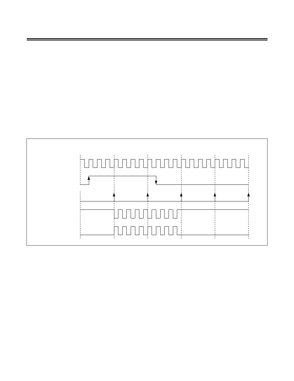
Figure 8-3. IR Transmission Waveform (IRCFME = 0)
IRMT = 3
0
1
1
1
3
3
2
2
0
0
0
IRDATA
IR INTERRUPT
IRTX
IRTXPOL = 1
IRTX
IRTXPOL = 0
CARRIER OUTPUT
(IRV)