3 timer b mode: up/down autoreload mode, 4 timer b mode: clock output mode, Figure 7-3 . timer b up/down autoreload mode -4 – Maxim Integrated MAXQ610 User Manual
Page 107: Maxq610 user’s guide
7-4
MAXQ610 User’s Guide
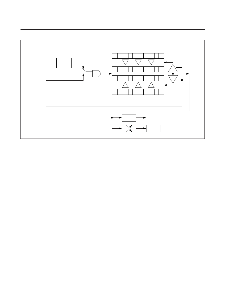
7.1.3 Timer B Mode: Up/Down Autoreload Mode
The up/down-count autoreload option is enabled by the DCEN (TBCN .4) bit . When DCEN is set to 1, Timer B counts up
or down as controlled by the state of TBB pin . TBB causes upward counting when a high is applied and down counting
when a low is applied . When DCEN = 0, Timer B only counts up .
When an upward counting overflow occurs (TBV overflow occurs after reaching TBR), a 0000h value loads into TBV . In
the down-count direction, an underflow occurs when TBV reaches 0000h . When an underflow occurs, the TBR value
is loaded into TBV counting continues .
Note that in this mode, the overflow/underflow output of the timer is provided to an edge-detection circuit as well as
to the TFB bit (TBCN .7) . This edge-detection circuit toggles the EXFB bit (TBCN .6) on every overflow or underflow .
Therefore, the EXFB bit behaves as a 17th bit of the counter, and can be used as such .
7.1.4 Timer B Mode: Clock Output Mode
Timer B can also be configured to drive a clock output on the TBA port pin as shown in Figure 7-4 . To configure Timer
B for this mode, first it must be set to 16-bit autoreload timer mode (CP/RLB = 0, C/TB = 0) . Next, the TBOE (TBCN .5)
bit must be set to 1 . The output state for this mode is always set to 1 each time the TBOE bit is changed from 0 to 1 .
TRB (TBCN .2) must also be set to 1 to enable the timer and the corresponding output . If the timer is stopped (TRB =
0) and subsequently restarted (TRB = 1) while leaving TBOE = 1, the previous timer clock output state is restored on
the TBA pin . The DCEN bit has no effect in this mode . This mode produces a 50% duty-cycle square-wave output . The
frequency of the square wave is given by the formula in the figure . Each timer overflow causes an edge transition on
the pin, i .e ., the state of the pin toggles . The timer overflow flag (TFB) is still set on an overflow in clock output mode,
however, the TBOE = 1 condition prevents this flag from causing an interrupt . The Timer B external interrupt is still
available for use when enabled (EXENB = 1) . Note that the EXFB flag can be set independent of the state of the TRB
bit (e .g ., EXFB can still be set on detection of a negative edge when TRB = 0) .
Figure 7-3. Timer B Up/Down Autoreload Mode
TFB
EXFB
TIMER B INTERRUPT
TBB PIN
1
TBA PIN
TRB
0
SYSTEM
CLOCK
CLOCK
PRESCALER
TBPS[2:0]
COUNT DIRECTION
(1 = UP, 0 = DOWN)
C/TB
15
0
TBR
(DOWN-COUNTING RELOAD)
(UP-COUNTING RELOAD VALUE)
TBV
15
0
0000h