1 timer b, 1 timer b mode: autoreload mode, 7 .1 timer b -2 – Maxim Integrated MAXQ610 User Manual
Page 105: 7 .1 .1 timer b mode: autoreload mode -2, Table 7-1 . timer/counter b mode summary -2, Maxq610 user’s guide, Table 7-1. timer/counter b mode summary
7-2
MAXQ610 User’s Guide
SECTION 7: TIMER/COUNTER TYPE B
The timer/counter module allows the MAXQ610 to control a 16-bit programmable timer/counter . The MAXQ610 imple-
ments two timer type B modules (“Timer B”): TB0 and TB1 .
7.1 Timer B
“Timer B” is an enhanced version of the MAXQ timer type 1 with modifications to support different input clock prescal-
ing and set/reset/compare output functionality . The new timer also counts in the range 0000h to TBR instead of TBR
to 0FFFFh .
The Timer B value that increments or decrements (depending on mode of operation) is contained in the 16-bit register,
TBV . Timer B is enabled by the Timer B run control (TRB) bit in the TBCN register . To support the basic functionality of
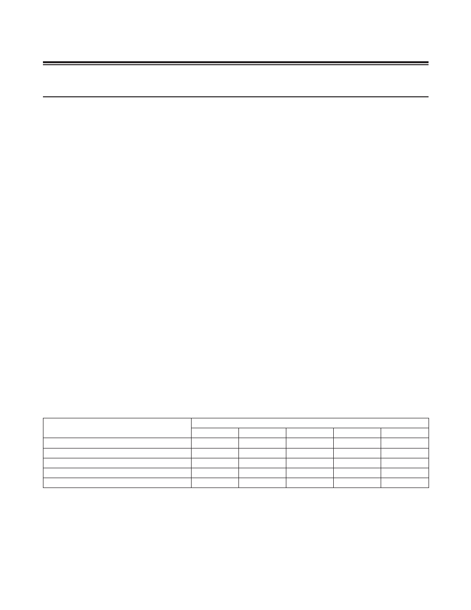
Timer B, a 16-bit capture/reload register (TBR) is provided . The basic Timer B operational modes and corresponding
TBCN register bit settings are shown in Table 7-1 . Following the table, each operational mode is described . The TBA
pin can be used as a counter input for any mode except for the Timer B clock output mode since this mode uses TBA
for clock output . The Timer B PWM output functionality is described in the sections that follow the basic modes .
7.1.1 Timer B Mode: Autoreload Mode
The Timer B autoreload mode is configured by setting the CP/RLB (TBCN .0) bit to 0 . In this mode, Timer B performs
a simple timer or counter function, but adds a separate 16-bit reload value and the ability to trigger a reload with an
external pin .
When initially enabled, Timer B starts counting from the TBV value . On overflow, TBV is reset and counting continues
from 0000h . When Timer B reaches an overflow state, i .e ., the TBR value is reached, the TFB flag is set in the follow-
ing system clock cycle . This flag can generate an interrupt if enabled . In addition, the timer restores its starting 0000h
value and begins timing (or counting) again . The overflow value is preloaded by software into the capture/reload reg-
ister, TBR . This register cannot be used for capture functionality while also performing autoreload, so these modes are
mutually exclusive .
When in autoreload mode, Timer B can also be forced to reload with the TBB pin . If EXENB (TBCN .3) is set to 1, then
a 1-to-0-transition on TBB causes a reload and the EXFB (TBCN .6) flag to be set . Note that the EXFB flag can be set
independent of the state of the TRB bit (e .g ., EXFB can still be set on detection of a negative edge when TRB = 0) .
Otherwise, the TBB pin is ignored .
If the C/TB bit (TBCN .15) is 0, the timer’s input clock is a function of the system clock . When C/TB = 1, pulses on the
TBA pin are counted . Counting or timing is enabled or disabled using the Timer B run control bit = TRB (TBCN .2) . This
mode, including the optional reload control, is illustrated in Figure 7-1 .
Table 7-1. Timer/Counter B Mode Summary
*For modes where the C/TB bit is x: When C/TB = 0, the timer input clock is a prescaled version of the system clock. When C/TB =
1, counter mode is enabled and the external TBA pin is counted.
TIMER B OPERATIONAL MODE
TBCN REGISTER BIT SETTINGS*
TBOE
DCEN
EXENB
C/TB
CP/RLB
Autoreload
0
0
0
x
0
Autoreload using TBB pin
0
0
1
x
0
Capture using TBB pin
0
0
1
x
1
Up/down count using TBB pin
0
1
0
x
0
Clock output on TBA pin
1
x
x
0
0