Maxq610 user’s guide – Maxim Integrated MAXQ610 User Manual
Page 102
6-9
MAXQ610 User’s Guide
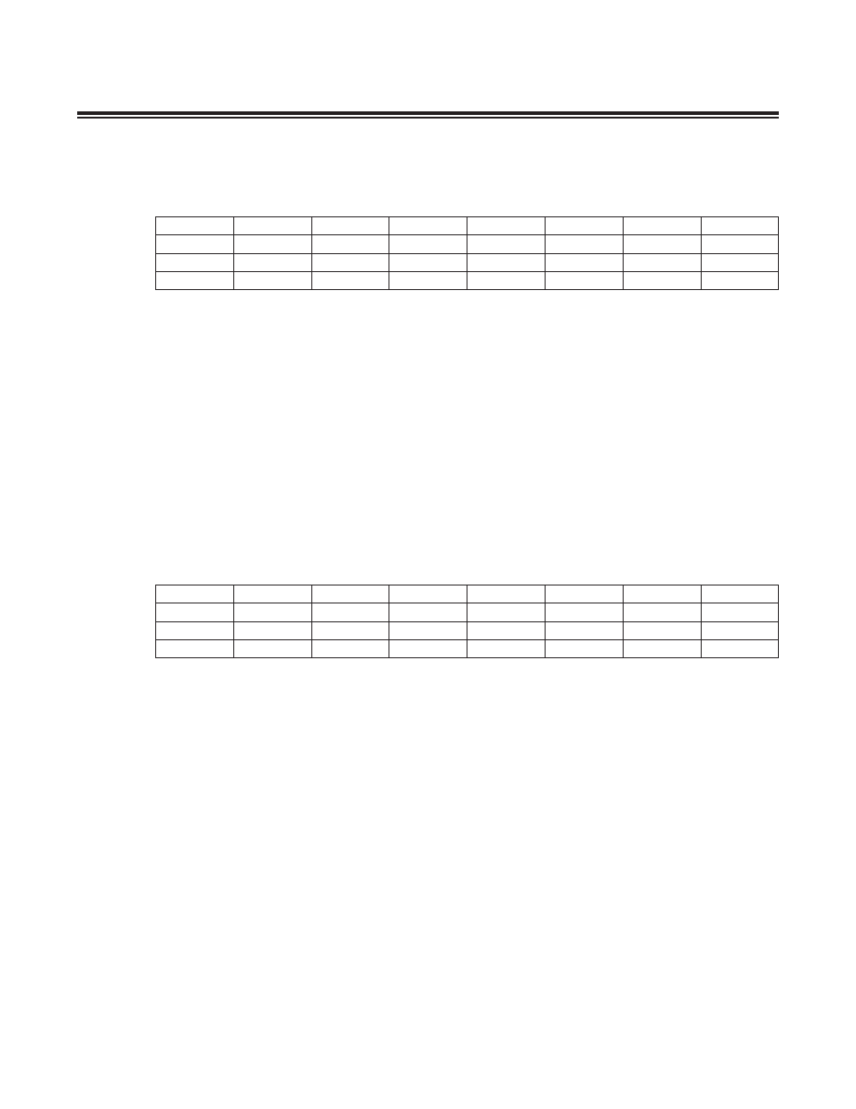
Each bit in this register controls the enable for one external interrupt . If a bit is set to 1, the corresponding interrupt is
enabled (if it is not otherwise masked) . If a bit is set to 0, its corresponding interrupt is disabled .
Bit 7: External Interrupt 15 Enable (EX15)
Bit 6: External Interrupt 14 Enable (EX14)
Bit 5: External Interrupt 13 Enable (EX13)
Bit 4: External Interrupt 12 Enable (EX12)
Bit 3: External Interrupt 11 Enable (EX11)
Bit 2: External Interrupt 10 Enable (EX10)
Bit 1: External Interrupt 9 Enable (EX9)
Bit 0: External Interrupt 8 Enable (EX8)
Each bit in this register controls the edge select mode for an external interrupt, as follows:
0 = The internal interrupt triggers on a rising (positive) edge .
1 = The external interrupt triggers on a negative (falling) edge .
Bit 7: Edge Select for External Interrupt 7 (IT7)
Bit 6: Edge Select for External Interrupt 6 (IT6)
Bit 5: Edge Select for External Interrupt 5 (IT5)
Bit 4: Edge Select for External Interrupt 4 (IT4)
Bit 3: Edge Select for External Interrupt 3 (IT3)
Bit 2: Edge Select for External Interrupt 2 (IT2)
Bit 1: Edge Select for External Interrupt 1 (IT1)
Bit 0: Edge Select for External Interrupt 0 (IT0)
Register Name
EIE1
Register Description
External Interrupt Enable 1 Register
Register Address
M0[09h]
Register Name
EIES0
Register Description
External Interrupt Edge Select 0 Register
Register Address
M0[0Ch]
Bit #
7
6
5
4
3
2
1
0
Name
EX15
EX14
EX13
EX12
EX11
EX10
EX9
EX8
Reset
0
0
0
0
0
0
0
0
Access
rw
rw
rw
rw
rw
rw
rw
rw
Bit #
7
6
5
4
3
2
1
0
Name
IT7
IT6
IT5
IT4
IT3
IT2
IT1
IT0
Reset
0
0
0
0
0
0
0
0
Access
rw
rw
rw
rw
rw
rw
rw
rw