2 run-test-idle, 3 ir-scan sequence, Figure 11-1 . tap controller state diagram -3 – Maxim Integrated MAXQ610 User Manual
Page 147: Maxq610 user’s guide
11-3
MAXQ610 User’s Guide
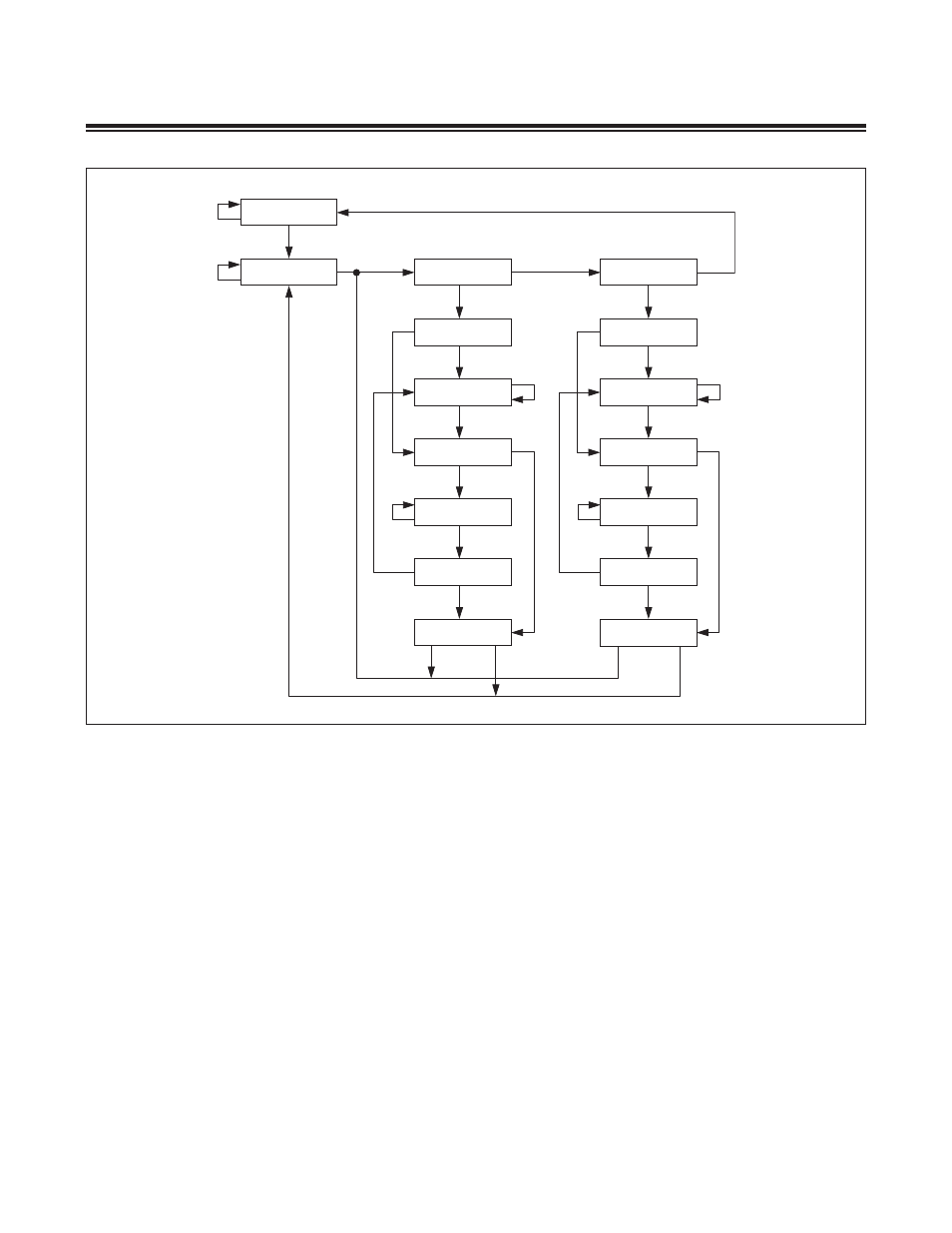
11.2.2 Run-Test-Idle
As illustrated in Figure 11-1, the run-test-idle state is simply an intermediate state for getting to one of the two state
sequences in which the controller performs meaningful operations:
• Controller state sequence (IR-scan) or
• Data register state sequence (DR-scan)
11.2.3 IR-Scan Sequence
The controller state sequence allows instructions (e .g ., debug and system programming) to be shifted into the instruc-
tion register starting from the select-IR-scan state . In the TAP, the instruction register is connected between the TDI
input and the TDO output . Inside the IR-scan sequence, the capture-IR state loads a fixed binary pattern (001b) into the
3-bit shift register and the shift-IR state causes shifting of TDI data into the shift register and serial output to TDO, least
significant bit first . Once the desired instruction is in the shift register, the instruction can be latched into the parallel
instruction register (IR[2:0]) on the falling edge of TCK in the update-IR state . The contents of the 3-bit instruction shift
register and parallel instruction register (IR[2:0]) are summarized with respect to the TAP controller states in Table 11-2 .
Figure 11-1. TAP Controller State Diagram
TEST-LOGIC-RESET
RUN-TEST-IDLE
SELECT-DR-SCAN
EXIT2-DR
CAPTURE-DR
SHIFT-DR
EXIT1-DR
PAUSE-DR
UPDATE-DR
SELECT-IR-SCAN
EXIT2-IR
CAPTURE-IR
SHIFT-IR
EXIT1-IR
PAUSE-IR
UPDATE-IR
1
0
1
1
1
1
1
1
1
1
1
1
1
1
1
0
0
0
0
0
0
0
0
0
0
0
0
0
1
1
0
0