Maxq610 user’s guide – Maxim Integrated MAXQ610 User Manual
Page 86
5-14
MAXQ610 User’s Guide
REGISTER
DESCRIPTION
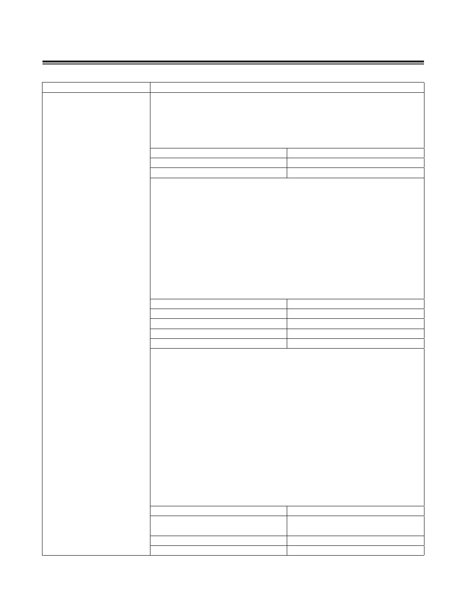
IRCN (04h, 02h)
Infrared Control Register (16-bit register)
Initialization:
This register is cleared to 0000h on all forms of reset .
Read/Write Access:
Unrestricted read/write .
IRCN.0 (IREN)
IR Enable. This register bit enables the IR module . Setting this bit to 1 starts the operating
mode as defined by IRMODE bit . Clearing this bit to 0 terminates IR operation .
IRCN.1 (IRMODE)
IR Mode. This register bit controls the IR module operation mode .
IRMODE
IR OPERATION MODE
0
Receive Mode
1
Transmit Mode
IRCN.2 (IRTXPOL)
IR TX Polarity Select. When the IR timer is enabled (IREN = 1), this bit selects the starting/
idle logic state, and the carrier polarity for the IRTX transmit output . This bit also impacts the
polarity of the IRTXM envelope when the independent modulator transmit output mode is
enabled (IRENV[1:0] = 01b or 10b) . When IRENV[1:0] = 01b or 10b, the latched IRDATA bit
is directly output to the IRTXM pin as the envelope when IRTXPOL = 0 . When IRTXPOL = 1,
the complement of the latched IRDATA bit is output .
IRCN.3 (IRDATA)
IR Data. This register bit defines how the carrier is modulated in transmit mode and in
receive mode, it contains the state of IRRX when a qualified capture event happens . When
IR transmit mode is in effect, setting IRDATA = 1 enables the output of the carrier module
(as affected by IRTXPOL) to be visible on the IRTX pin . When IRDATA = 0, the IR module is
put in the idle state and IRTXPOL is output onto IRTX . In receive mode, the IRDATA bit con-
tains the latched state of the IRRX pin each time a capture event occurs .
IRCN.5 to IRCN.4 (IRRXSEL[1:0])
IR Receive Edge Select Bits. These bits define which edge of the input signal trigger a
receive capture function when enabled .
IRRXSEL[1:0]
IR RECEIVE MODE
00
Trigger on falling edge
01
Trigger on rising edge
10
Trigger on both rising and falling edge
11
Reserved (disables edge detection)
IRCN.6 (IRCFME)
IR Clock Frequency Mux Enable. In receive mode, setting this bit to 1 enables direct
clocking of the IRV register using the defined IRCLK during the IR receive operation .
Clearing this bit to 0 results in IRV counting of the IRCA-defined carrier during the receive
operation . Using IRCFME = 1 allows IRCLK clock resolution when capturing whereas
IRCFME = 0 allows only (IRCLK/2) resolution when IRCA = 0000h . In transmit mode, set-
ting this bit to 1 enables direct clocking of the IRV register down counter with IRCLK so
that intervals can be generated with IRCLK resolution . When this bit is cleared to 0, the IRV
down counter is clocked with the IRCA-defined carrier clock, resulting in IRV interval gen-
eration according to the defined carrier frequency .
IRCN.7 (IRXRL)
IR Receive Reload Enable. Setting this bit to 1 enables automatic reload of the IRV register
with 0000h whenever a qualified edge event capture occurs during the IR receive opera-
tion . If IRXRL = 0, the IRV register is not reloaded with 0000h, but continues running during
the IR receive operation .
IRCN.9 to IRCN.8 (IRENV[1:0])
IR Envelope Mode Bits 1:0. Setting either of these bits (but not both) to 1 enables the
envelope modulation signal (based upon the IRDATA and IRTXPOL bits) to be output sepa-
rately to the IRTXM pin during transmit mode . When the bits are both cleared to 0 or set to
1, the standard internal modulation is performed during IR transmit mode and the envelope
signal is not output to the IRTXM pin . When the envelope mode is enabled, it is possible to
output either the modulated or unmodulated carrier to the IRTX pin (see table) .
IRENV[1:0]
IRTX OUTPUT
00 or 11
Envelope mode disabled .
Standard IRTX modulation (default) .
01
Standard IRTX modulation .
10
Constant IRTX carrier (unmodulated) .