Maxq610 user’s guide – Maxim Integrated MAXQ610 User Manual
Page 89
5-17
MAXQ610 User’s Guide
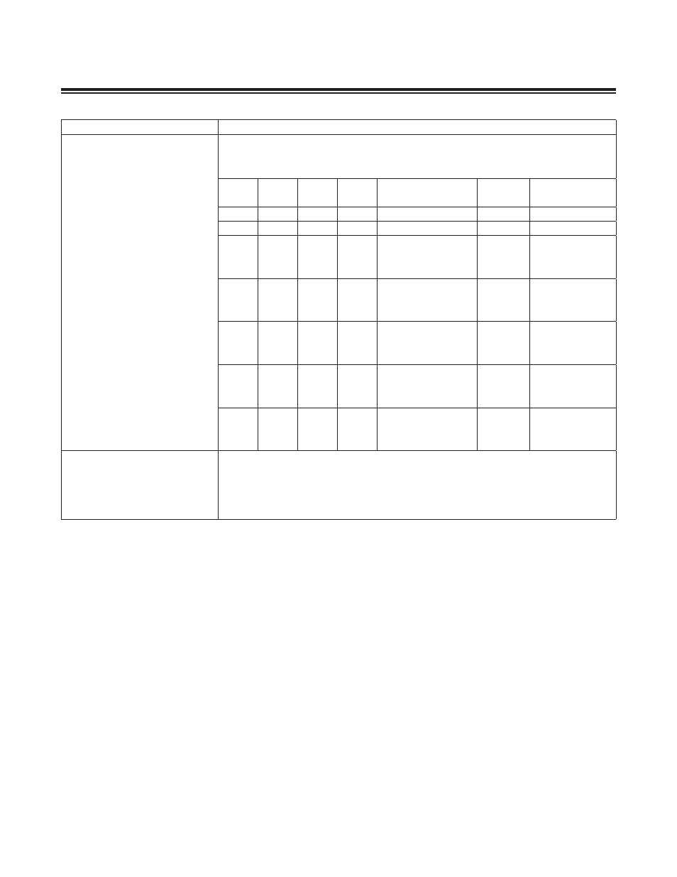
REGISTER
DESCRIPTION
SCON0.6 (SM1)
SCON0.7 (SM0/FE)
Serial Port 0 Mode Bits 1:0 (when FEDE is 0) . When FEDE is set to 1, this bit is the
Framing Error Flag that is set upon detection of an invalid stop bit . It must be cleared by
software . Modification of this bit when FEDE is set has no effect on the serial mode .
MODE
SM2
SM1
SM0
FUNCTION
LENGTH
(BITS)
PERIOD
0
0
0
0
Synchronous
8
12 system clocks
0
1
0
0
Synchronous
8
4 system clocks
1
x
1
0
Asynchronous
10
64/16 baud clocks
(SMOD = 0/1)
2
0
0
1
Asynchronous
11
64/32 system
clocks (SMOD =
0/1)
2
1
0
1
Asynchronous (MP)
11
64/32 system
clocks (SMOD =
0/1)
3
0
1
1
Asynchronous
11
64/16 baud clocks
(SMOD = 0/1)
3
1
1
1
Asynchronous (MP)
11
64/16 baud clocks
(SMOD = 0/1)
SBUF0 (01h, 03h)
Serial Data Buffer 0
Initialization:
This buffer is cleared to 00h on all forms of reset .
Read/Write Access:
Unrestricted read/write .
SBUF0.7 to SBUF0.0
Serial Data Buffer 0 Bits 7:0. Data for serial port 0 is read from or written to this location .
The serial transmit and receive buffers are separate but both are addressed at this location .
- DS80C390 (58 pages)
- DS5001FP (26 pages)
- MAX1416 (14 pages)
- MAX5865 (18 pages)
- DS33Z41 (167 pages)
- MAX1202 (7 pages)
- USBTO232 (31 pages)
- HFAN-09.5.0: Pattern Creator/Converter Software (8 pages)
- MAX-IDE MAXQ Microcontrollers (11 pages)
- MAX6876 Power-Supply Tracker/Sequencer (6 pages)
- MAX6877 Power-Supply Tracker/Sequencer (3 pages)
- 78Q8430 ARM9(920T) Linux Driver Diagnostic Guide (19 pages)
- 78Q8430 Software Driver (54 pages)
- 78Q8430 ST 5100/OS-20 with NexGen TCP/IP Stack (28 pages)
- 6612_OMU_S2_URT_V1_13 (56 pages)
- 6612_OMU_S2+2_URT_V1_14 (58 pages)
- 71M6511 Power Meter IC Family Software (137 pages)
- 71M65xx ADM51 ICE Safety Notice (2 pages)
- 71M6511 2-Layer Demo Board (2 pages)
- 71M6511 4-Layer Demo Board (2 pages)
- 78Q8430 Linux Driver ARM Platform (22 pages)
- 71M6513 Demo Board (2 pages)
- 71M6521DE Energy Meter IC Family Software (138 pages)
- 71M6521 Demo Board (2 pages)
- 71M6531 Demo Board (2 pages)
- 71M6531 Energy Meter IC Family Software (116 pages)
- 71M6533 Demo Board (2 pages)
- 71M6534H Demo Board (2 pages)
- 71M6515H Demo Board (2 pages)
- 73S1209F Evaluation Board (2 pages)
- 73S12xxF (38 pages)
- 73S12xxF Software (93 pages)
- 73S1210F Evaluation Board Lite (2 pages)
- 73S1210F Evaluation Board (2 pages)
- 73S1210F Multi-SAM Evaluation Board Lite (2 pages)
- 73S12xxF USB-CCID Linux DFU Host Application (8 pages)
- 73S1215F Device Firmware Upgrade Host Driver/Application (10 pages)
- 73S12xxF USB-CCID Host GUI (22 pages)
- 73S1215F Windows XP 32 USB CCID and DFU Drivers (15 pages)
- 73S1215F CCID USB Linux Driver (16 pages)
- 73S1215F Evaluation Board (2 pages)
- 73S1215F Evaluation Board Lite (2 pages)
- 73S1217F Evaluation Board (2 pages)
- 73S1217F Evaluation Board Lite (2 pages)
- MAXQ Family (216 pages)