4 usart peripheral registers, 1 serial control register (scon), 9 .4 usart peripheral registers -10 – Maxim Integrated MAXQ610 User Manual
Page 135: 9 .4 .1 serial control register (scon) -10, Maxq610 user’s guide
9-10
MAXQ610 User’s Guide
The FE bit is set to a 1 when a framing error occurs . It must be cleared by software . Note that the FEDE state must be
1 while reading or writing the FE bit . Also note that receiving a properly framed serial word does not clear the FE bit .
This must be done in software .
9.4 USART Peripheral Registers
9.4.1 Serial Control Register (SCON)
Bit 7: Framing Error Flag (FE) (FEDE = 1). This bit is set upon detection of an invalid stop bit . It must be cleared by
software . Modification of this bit when FEDE is set has no effect on the serial mode setting .
Bit 7: Serial Port 0 Mode Bit 0 (SM0) (FEDE = 0). This bit is used in conjunction with the SM2 and SM1 bits to define
the serial mode .
Bits 6:5: Serial Port 0 Mode Bits 2:1 (SM[2:1]). Setting this bit in mode 1 ignores reception if an invalid stop bit is
detected . Setting this bit in mode 2 or 3 enables multiprocessor communications, and prevents the RI bit from being
set and the interrupt from being asserted if the 9th bit received is 0 .
This bit also used to support mode 0 for clock selection:
0 = serial clock is system clock divided by 12
1 = serial clock is system clock divided by 4
Bit 4: Receive Enable (REN)
0 = serial port receiver disabled
1 = serial port receiver enabled for modes 1, 2, and 3 . Initiate synchronous reception for mode 0 (if RI = 0) .
Bit 3: 9th Transmission Bit State (TB8). This bit defines the state of the 9th transmission bit in serial port modes 2
and 3 .
Bit 2: 9th Received Bit State (RB8). This bit identifies the state of the 9th bit of received data in serial port modes 2
and 3 . When SM2 is 0, it is the state of the stop bit in mode 1 . This bit has no meaning in mode 0 .
Bit 1: Transmit Interrupt Flag (TI). This bit indicates that the data in the serial port data buffer has been completely
shifted out . It is set at the end of the last data bit for all modes of operation and must be cleared by software once set .
7
0
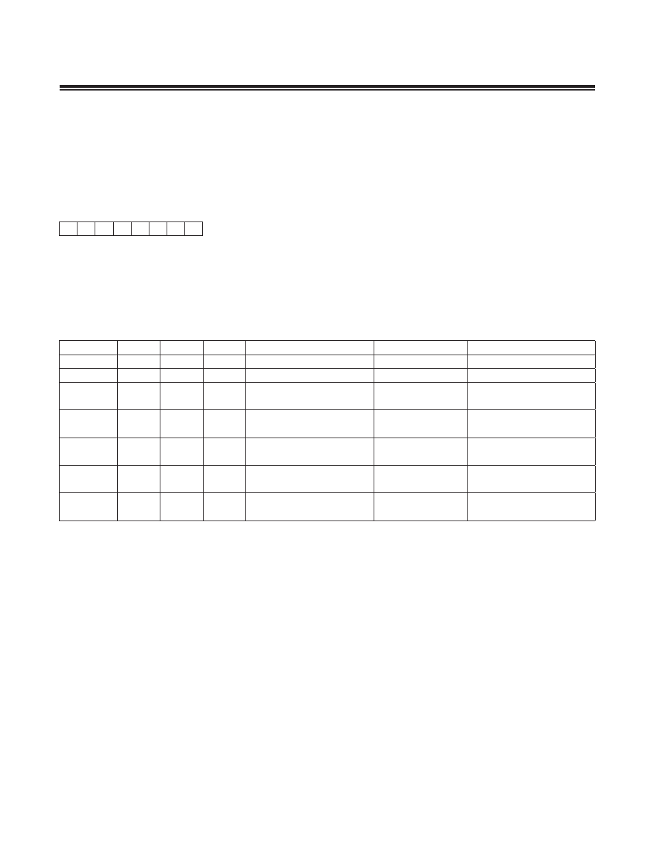
Serial Control Register (SCON)
0
0
0
0
0
0
0
0
Power-On Reset and System Resets
rw rw rw rw rw rw rw rw
Read (r), Write (w), or Special (s) access
MODE
SM2
SM1
SM0
FUNCTION
LENGTH (BITS)
PERIOD
0
0
0
0
Synchronous
8
12 system clock
0
1
0
0
Synchronous
8
4 system clock
1
X
1
0
Asynchronous
10
64/16 baud clock
(SMOD = 0/1)
2
0
0
1
Asynchronous
11
64/32 system clock
(SMOD = 0/1)
2
1
0
1
Asynchronous (MP)
11
64/32 system clock
(SMOD = 0/1)
3
0
1
1
Asynchronous
11
64/16 baud clock
(SMOD = 0/1)
3
1
1
1
Asynchronous (MP)
11
64/16 baud clock
(SMOD = 0/1)