Ać13, Plc programming considerations appendix a, Input data (block transfer read) – Rockwell Automation 2711 PANELBUILDER SOFTWARE USER MANUAL User Manual
Page 377
PLC Programming Considerations
Appendix A
A-13
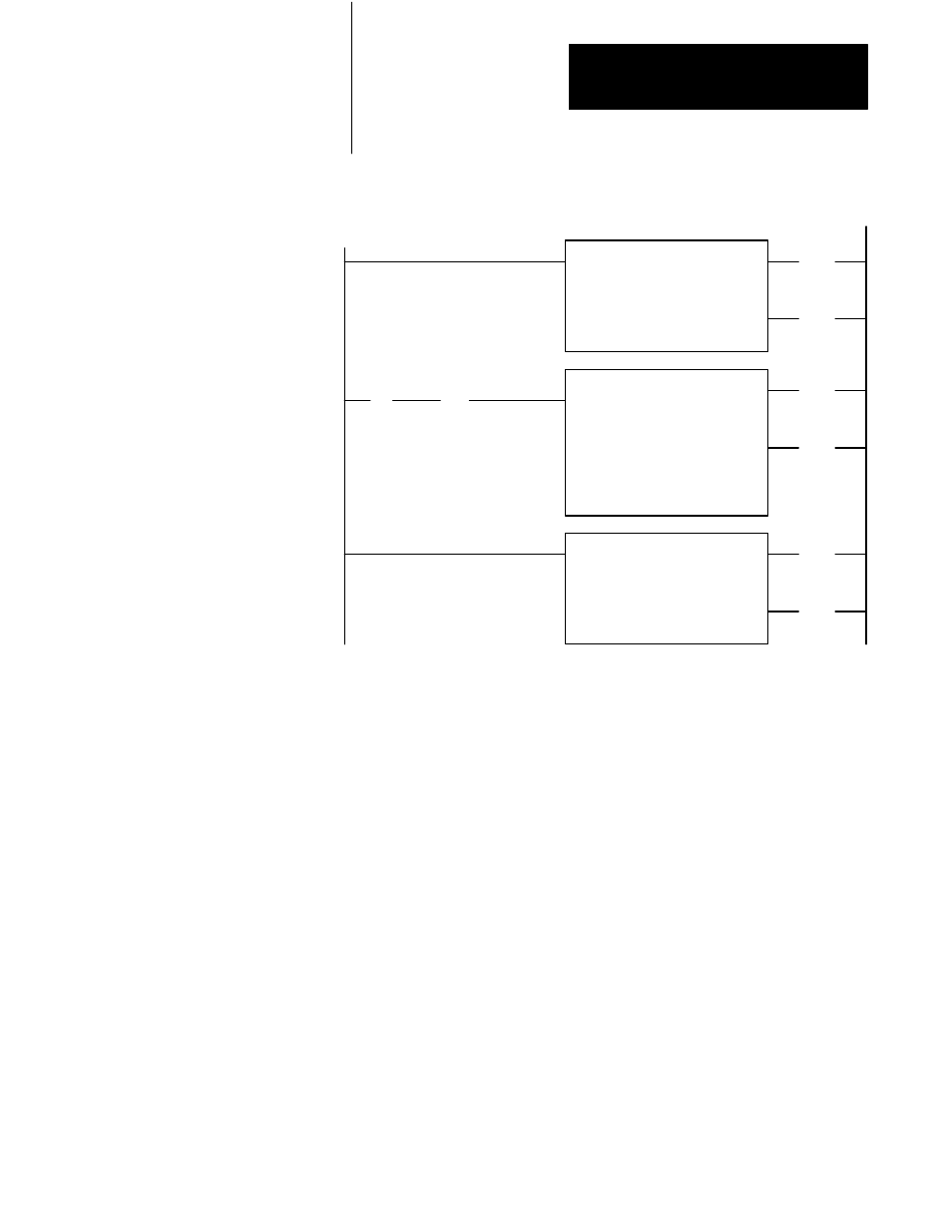
Figure A.8
Block Transfer Programming Example for Local PLCĆ2 Family Processor
DATA ADDR:
0030
MODULE ADDR:
131
BLOCK LENGTH:
24
FILE:
300- 327
BLOCK XFER READ
Local Processor
013
(EN)
17
Fault Bit
305
] / [
BTR
Done Bit
113
] [
17
00
20218
113
(DN)
17
COUNTER ADDR: 0040
POSITION:
001
FILE LENGTH:
19
FILE A: 0305- 0327
FILE R: 0405- 0427
RATE PER SCAN: 0
FILE TO FILE MOVE
0040
(EN)
17
0040
(DN)
15
DATA ADDR:
0031
MODULE ADDR:
131
BLOCK LENGTH:
24
FILE:
200- 227
BLOCK XFER WRITE
Buffer File
CNTL
(EN)
16
113
(DN)
16
Input Data (Block Transfer Read)
The 1771-SN formats input data received from the PanelView terminals
and block transfers this data to the PLC processor when enabled by your
ladder diagram program. Eight words are reserved for I/O data from each
full remote I/O chassis (Figure A.9). Do not use the first eight words (0
through 7 octal) for data from input modules. The remaining words (10–
77 octal) correspond to Remote I/O rack numbers 1–7. For example, word
10 (octal) corresponds to module group 0 of rack number 1. The most
significant byte is slot 1, the least significant byte is slot 0.
The reason for the additional length of BTR and BTW files is addressing
convenience. Word addresses for assigned rack 1 are 10–17, assigned rack
2 are 20–27, assigned rack 3 are 30–37, etc., in both files.