Creating a sample application file chapter 5 – Rockwell Automation 2711 PANELBUILDER SOFTWARE USER MANUAL User Manual
Page 142
Creating a Sample Application File
Chapter 5
5-28
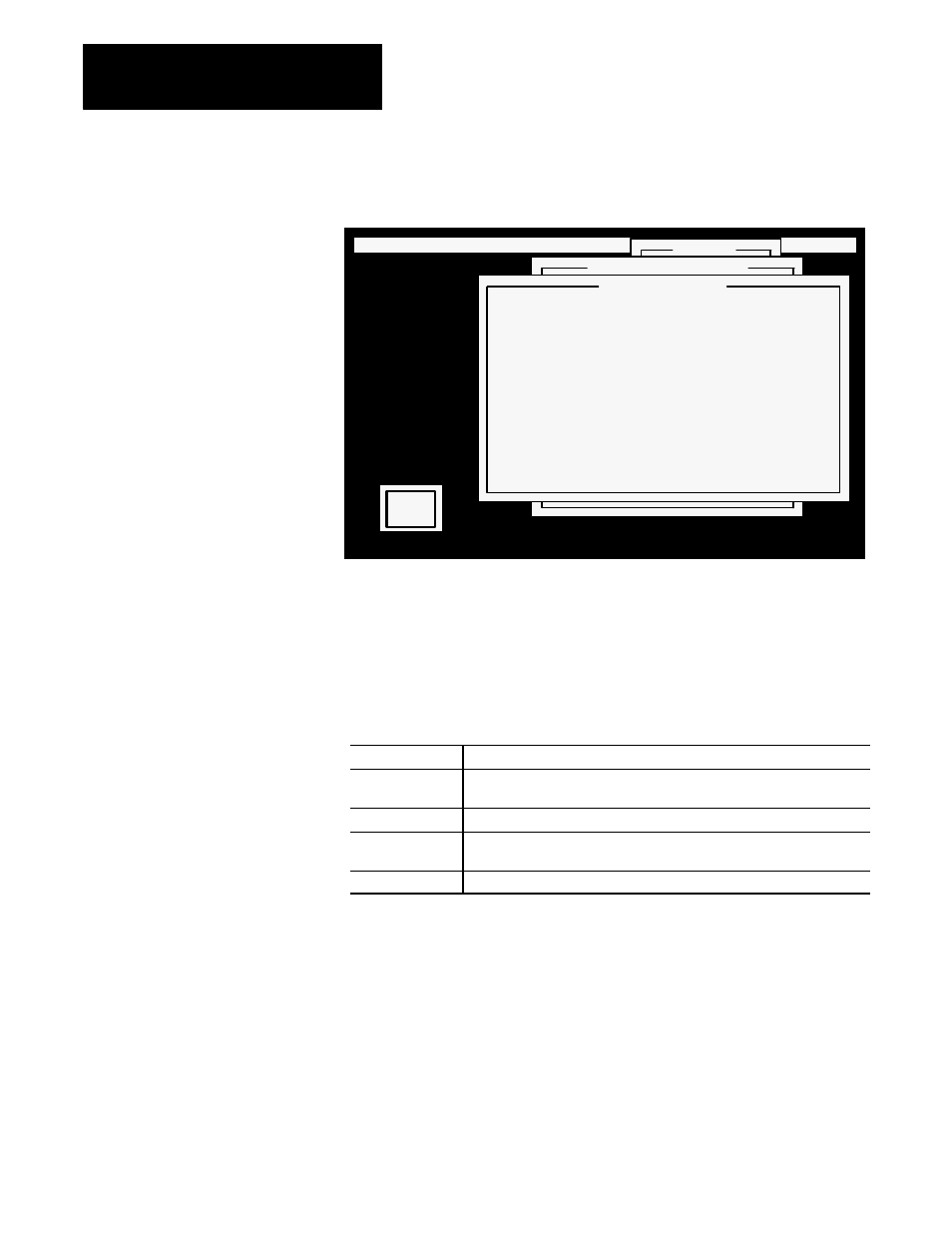
Figure 5.39
Setting the Address Map for Rack 1
22073
OBJECT MENU: Move & Size Look Text Screen Utility Exit
C
.
O
.
N
.
V
.
E
.
Y
.
O
.
R
.
G
.
C
.
O
.
N
.
T
.
R
.
O
.
L
.
S
.
G
. . . . . . . . . . . . . . . . . . . . . . . . . . . . . . . . . . . . . . . . . . .
Address
Button Control Address
View Address Map
Communications:Discrete
Input/Output: Input
Rack: 1
Bit
17 16 15 14 13 12 11 10 7 6 5 4 3 2 1 0
0 . . . . . . . . . . . . . . . *
W
1 b b b b b b b b . . . . . . . .
O
2 x x x x x x x x x x x x x x x x
R
3 x x x x x x x x x x x x x x x x
D
4 x x x x x x x x x x x x x x x x
5 x x x x x x x x x x x x x x x x
6 x x x x x x x x x x x x x x x x
7 x x x x x x x x x x x x x x x x
FRONT
O
.
N
.
The Address Map indicates the amount of space you’ve allocated in the
Input Image Table for rack 1. Table 5.A explains the different symbols
used in the Address Map.
Table 5.A
Symbols Used in the Address Map
This symbol:
means:
ББББББ
ББББББ
x
ББББББББББББББББББ
ББББББББББББББББББ
the bits are outside the available address range. They show the modules
that were NOT allocated to the PanelView terminal
ББББББ
ББББББ
.
ББББББББББББББББББ
ББББББББББББББББББ
the bits are still available
ББББББ
Б
ББББ
Б
ББББББ
*
ББББББББББББББББББ
Б
ББББББББББББББББ
Б
ББББББББББББББББББ
the bits that have been allocated to Objects, Windows, and PLC Control
Options
ББББББ
ББББББ
b
ББББББББББББББББББ
ББББББББББББББББББ
the bits that have been used as a block transfer control byte
In the Address Map, you can see the one bit that was allocated for the push
button in the Input Image Table.
Press Esc to remove the Address Map from the screen, then choose Quit to
close the Button Control Address menu.
From the Address menu, choose Indicator State Address. You’ll find the
addresses on the Object Address List shown in Figure 4.14, Chapter 4,
Planning Your Application.