Planning your application chapter 4 – Rockwell Automation 2711 PANELBUILDER SOFTWARE USER MANUAL User Manual
Page 107
Planning Your Application
Chapter 4
4-32
Figure 4.13
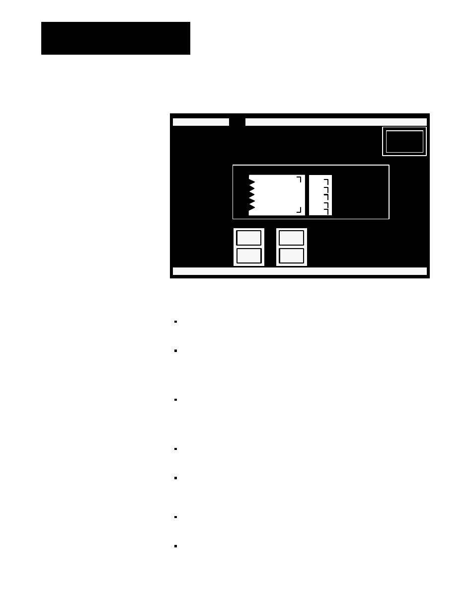
Screen 3 The Pump Controls Screen
22109
V1 Size: 2,243 Screen: 3 PUMP Oct 15 1992 12:31
SCREEN MENU:
Add
Edit Move Delete Memorize Recall Options Exit
UP
DOWN
CROSSOVR
MAIN
OUTPUT
INPUT
BACKUP
_NNNN
_NNNN
_NNNN
_NNNN
_NNNN
MAIN
SCREEN
ON
ON
ON
ON
ON
PUMP_CONTROLS
PRESSURE_(PSI):
P
.
U
.
M
.
P
.
G
.
C
.
O
.
N
.
T
.
R
.
O
.
L
.
S
.
. . . . . . . . . . . . . . . . . . . . . . . . . . . . . . .
O
.
N
.
O
.
F
.
F
.
Screen 3 consists of:
three
Text
objects including the screen title: PUMP CONTROLS, and
the two text labels: PUMP CONTROLS and PRESSURE (PSI)
one
Control List Selector Without Enter with five selections labeled
CROSSOVER, MAIN, OUTPUT, INPUT, and BACKUP. The Control
Selector’s two cursor control buttons are assigned to F3 and F11 and are
labeled UP and DOWN
five
Multi-State
Indicators positioned immediately to the right of the
Control List Selector Without Enter Button. Each Multi-State Indicator
has been assigned two states. One state is labeled ON, the other OFF.
More states could be assigned
five Numeric Display Objects positioned to the right of the Control List
Selector Without Enter Button and Multi-State Indicators
one
Box
object
surrounding the Control List Selector Without Enter
Button, the Multi-State Indicators, the Numeric Displays, and two of the
text objects
two Momentary Push Buttons (Normally Open) labeled ON and OFF
assigned to F4 and F12
one Return to Previous Screen button labeled MAIN SCREEN, assigned
to F17