Information and alarm windows chapter 7 – Rockwell Automation 2711 PANELBUILDER SOFTWARE USER MANUAL User Manual
Page 247
Information and Alarm Windows
Chapter 7
7-39
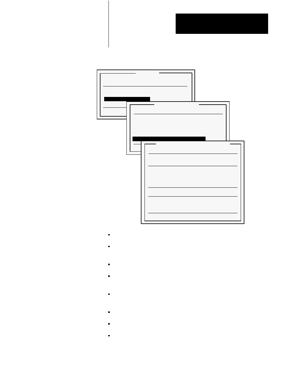
Figure 7.32
QTY/TIME Reset to PLC Controller Address Assignment Menu
22598
Windows
Alarm Window
254
Enable
Information Window
Enable
Terminal Fault Window
Alarm History Screen
Alarm Status Screen
Numeric and Security Entry Window
Quit
Alarm Status Screen
Screen Number
254
Foreground Color
Black
Background Color
Cyan
PLC Controlled QTY/Time Reset
Disable
QTY/TIME Reset Button
Enable
QTY/TIME Reset to PLC Controller
Enable
Quit
QTY/TIME Reset to PLC Controller
Current Address
Unassigned Address
Data Type
Bit
Communications
Discrete
Input/Output
Input
Rack
1
Start Word
0
Start Bit
0
Number of Bits
1
Update Address
View Address Map
Delete Address
Quit
Data Type is fixed at Bit.
Communications specifies whether you want a Discrete or Block
Transfer.
Input/Output—only a single Input address is permitted.
Rack specifies the rack number. This option appears on the menu only
if you have specified that this is a Discrete address.
File specifies the block transfer file. This option appears on the menu
only if you specified that this is a Block Transfer Address.
Start Word specifies the starting word for the address.
Start Bit specifies the starting bit within the word for the address.
Number of Bits is fixed at 1.