10ć23 – Rockwell Automation 2711 PANELBUILDER SOFTWARE USER MANUAL User Manual
Page 288
The Objects
Chapter 10
10-23
BCD: 4 bits
Bit: 9 bits; (all bits off = state 0) if more than one bit is on at a time, the
least significant bit’s state is displayed
The following table indicates the state number and the required bit pattern
for each data type:
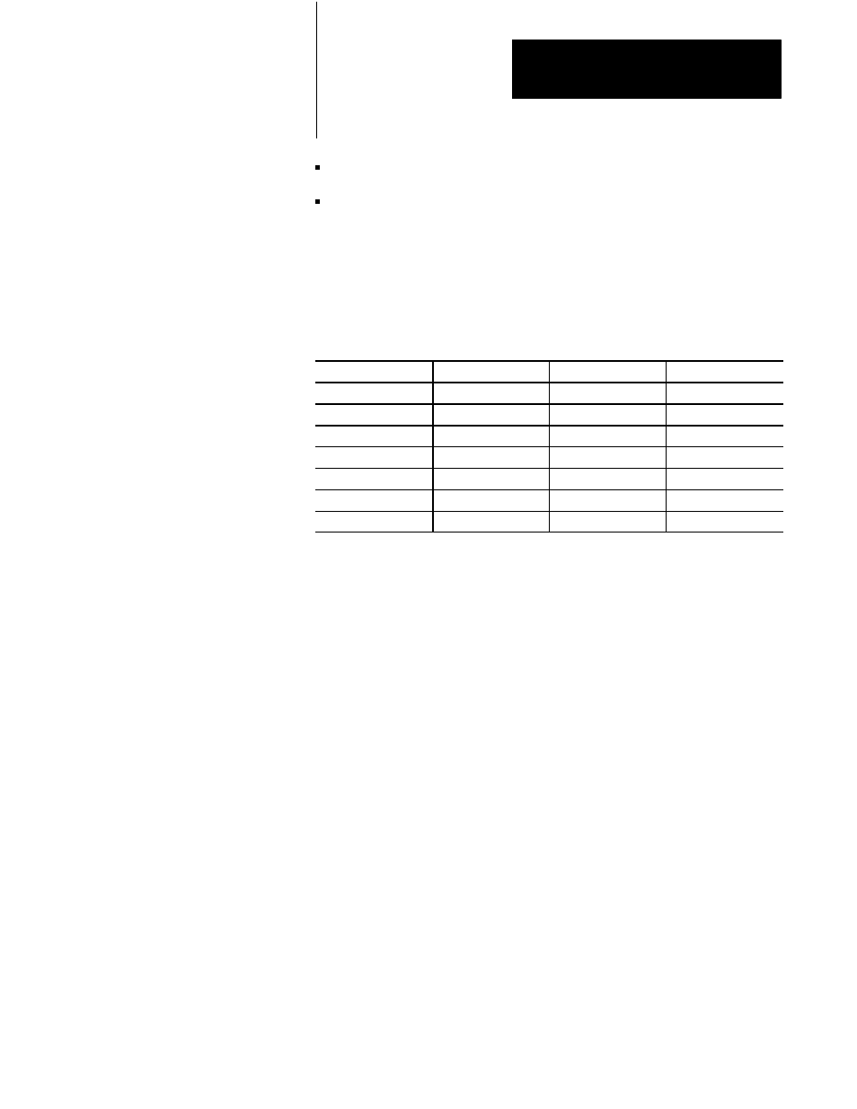
Table 10.C
Bit Patterns for Each State: Binary, BCD and Bit Data Type
State
Binary
BCD
Bits
0
0000
0000
000000000
1
0001
0001
000000001
2
0010
0010
000000010
3
0011
0011
000000100
.
.
.
.
.
.
.
.
9
1001
1001
100000000
If the value indicated by the PLC controller is not within the indicator’s
range, the colors and attributes of the highest numbered state will be
displayed but the text inside the indicator will be blanked.
List Indicator
The List Indicator is used to display the current status or state of a
particular PLC operation. The list can have up to 24 items, one of which is
highlighted to indicate that it is currently in effect. The operator can see all
the possible states for a particular operation, and see which state is current.
The List Indicator is similar to the Control List Selector, except that the
PLC controller, rather than the operator, controls the display.
The value of the object’s PLC address, the state number, and the
configuration of Top Position Value determine which entry is highlighted.
This object supports three data types, binary, BCD, and bit. Like the
Control List Selector object and the Multi-State Indicator, the maximum
number of states is determined by the data type and the number of bits
assigned. See Table 10.B for a list of valid state values for states 0 to 9. If
more than one bit is on at a time, the least significant bit’s state is
displayed.