Operator’s manual – Teledyne LeCroy WaveExpert 100H Operators Manual User Manual
Page 86
Operator’s Manual
84
WE-OM-E Rev A
11. The rise time control allows impedance measurements with specific rise times. Generally,
increasing the rise time will reduce the impedance variations measured on the instrument
display. The rise time can be set from 20 ps to 10 ns.
S-parameters
S-parameters (Scattering parameters) are ratios of power that represent the frequency
performance of a device. Due to the advent of high data rates in serial applications, S-parameters
have become a common specification, in addition to Jitter, for characterizing performance of serial
networks. Typical S-parameter terms include Return Loss, Insertion Loss, and Crosstalk.
S-parameters on the WaveExpert are obtained by applying an FFT to the TDR data to convert the
time response of a device into its frequency response. The calibration process compensates the
measured traces for any imperfections in the TDR system including the cables and connectors
between the instrument and the DUT.
Single-Ended S-parameters
S-parameters are depicted as S
xy
, which denotes the ratio of power at output port x, when an input
signal is applied at port y.
For example, a one-port single-ended device has only one S-parameter, S
11
where S
11
= b1/a1 — ratio of output signal (b1) at port 1 when an input stimulus (a1) is
applied to port 1, which in time-domain representation is the TDR at port 1 of the device.
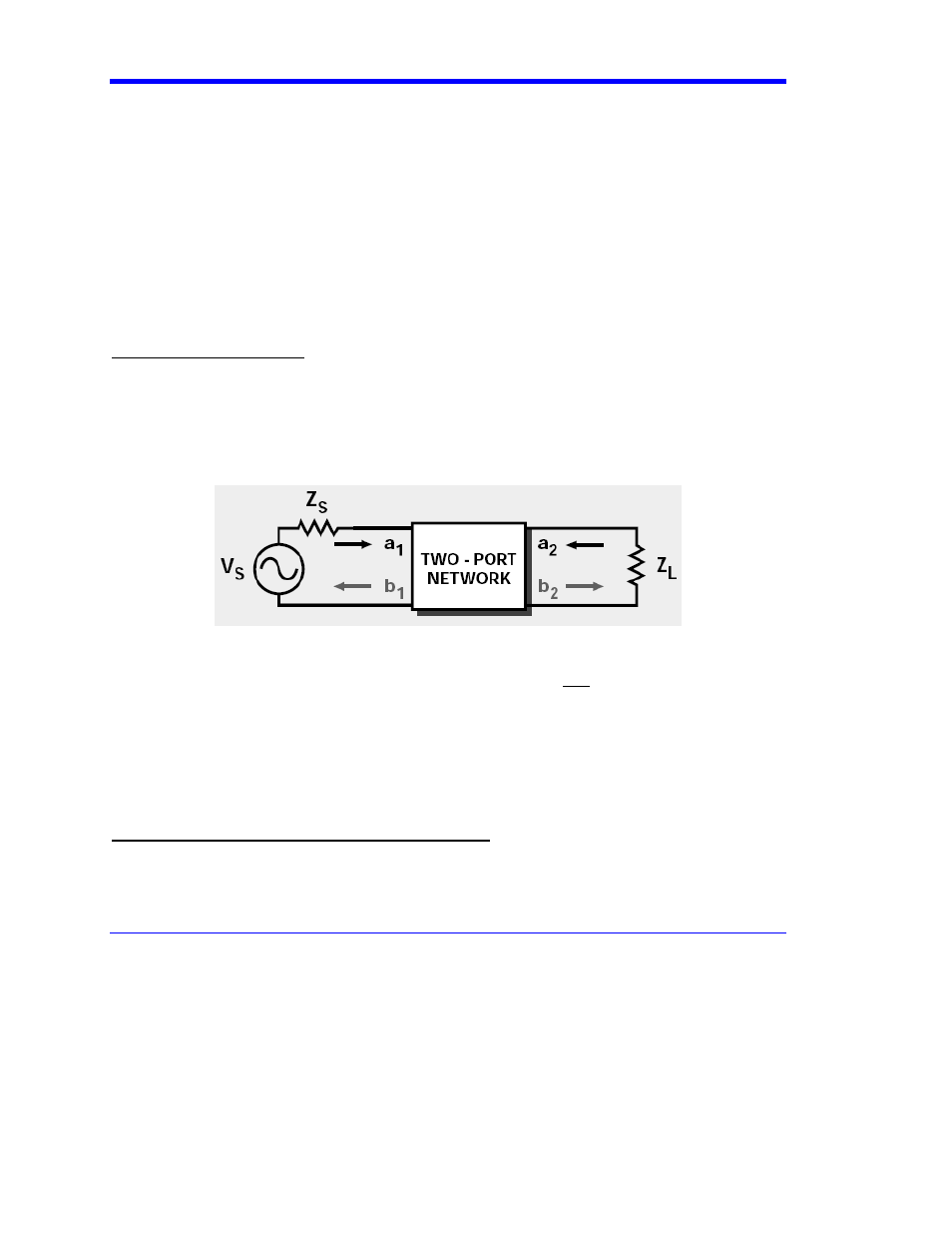
All input signals to a test port are designated “a”, and all output signals at a port are designated “b”.
Similarly, for a two-port single-ended network, there are a total of four S-parameters (see figure
above):
S
11
= b1/a1 (Return Loss at Port 1)
S
21
= b2/a1 (Insertion Loss of signal from port 1 to port 2)
S
12
= b1/a2 (Reverse Insertion Loss from port 2 to port 1)
S
22
= b2/a2 (Reverse Return Loss)
Balanced (Differential & Common mode) S-parameters
In cases of balanced devices, the stimulus is made up of two ports carrying either common signals
(in-phase stimulus) or Differential Signals (out-of-phase stimulus). The ideal mode of operation is to
pass all Differential data, while rejecting all common-mode signals.