Teledyne LeCroy WaveExpert 100H Operators Manual User Manual
Page 75
Wave Expert
WE-OM-E Rev A
73
calibration is available as part of the Calibration feature in TDR mode, which also handles the TDR
impedance calibration for the measurement setup.
Single-ended TDR
measurements can be made by adjusting the acquisition window, such that the
entire time domain response of the DUT is captured on the screen. This can be tested by
connecting the channels to the input of the DUT, while leaving the output end either open or
connected to a short, then adjusting the timebase such that the Open or Short response at the
output of the DUT is also visible on screen.
Number of points in TDR mode can be selected by the “Max Sample Points” control in the
Horizontal dialog. More points results in better time domain resolution for quantifying device
discontinuities, albeit limited by the rise time of the step pulse. Given the 20 ps rise time of the TDR
step generator, sufficient resolution must be used in the acquisition system. A time resolution of 2
ps per samples or less is recommended.
Differential TDR measurements
will require at least two channels to be selected and turned ON in
the TDR setup menu. The two channels need to be deskewed to make accurate differential
measurements of the DUT, as described in the next section..
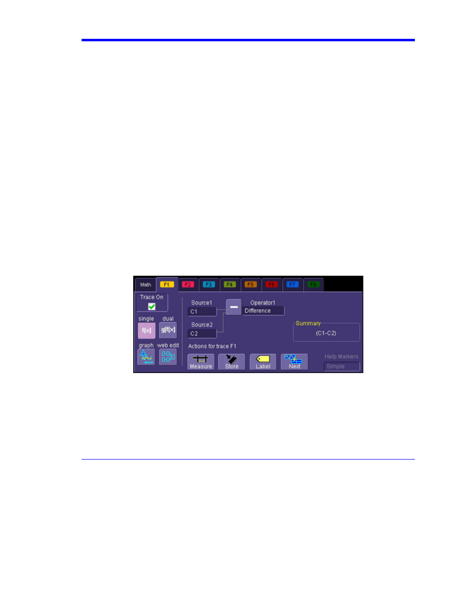
Once the channels are deskewed, a Differential TDR measurement can be made by selecting the
Difference math function to subtract the responses of the two individual channels to produce a
differential response. When making an Impedance measurement, the two individual impedance
traces must be added by selecting the Sum math function to calculate the Differential Impedance
response. Refer to “Waveform Math” in the WaveExpert Operator’s Manual. The differential
response is automatically calculated if a differential Reference Plane calibration is performed, in
which case you can skip this step. See Reference Plane Calibration section.
Math setup dialog