Operator’s manual – Teledyne LeCroy WaveExpert 100H Operators Manual User Manual
Page 228
Operator’s Manual
226
WE-OM-E Rev A
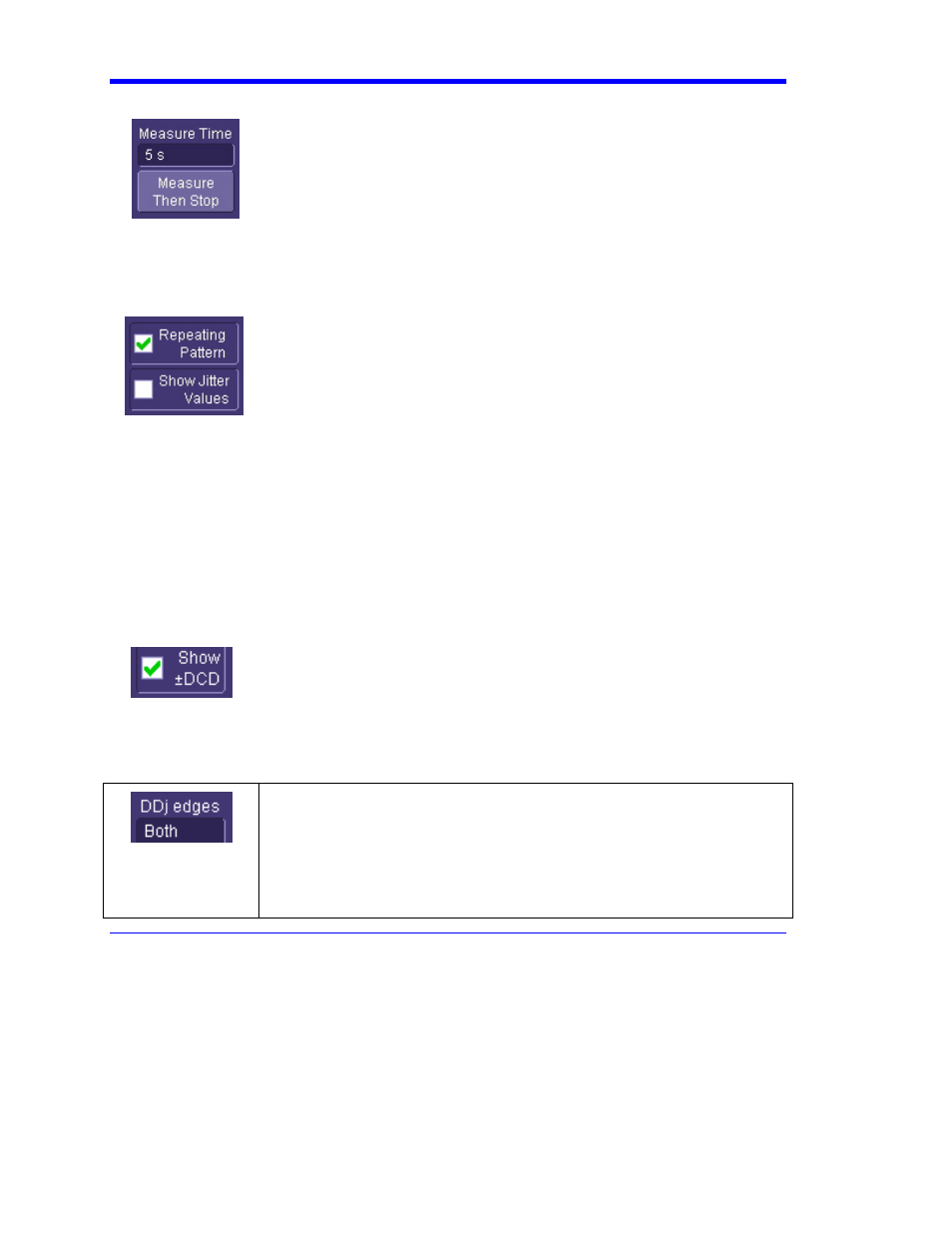
Measure Time
The Measure Time controls are used to set up times for jitter tests. The
Measure Then Stop button runs the acquisition system for the amount of
time set in the Measure Time control, and then stops by placing the trigger
in Stop mode. During acquisition, the eye pattern and jitter histogram are
updated very rapidly, but no measurements are made until the acquisition
is complete. On completion of acquiring data for the specified time, the
jitter measurements are made. The advantage of this control is that the
maximum data set is taken for the selected time period because there is no
measurement overhead.
Repeating Pattern
The two controls in this section select the jitter parameter view. By default,
both of these controls are checked. Show Jitter Values toggles the
display of the jitter parameters at the bottom of the grid on and off.
Repeating Pattern selects the type of jitter breakdown that is performed.
When the data signal consists of a repeating pattern, each edge of the
pattern is measured separately to determine its jitter distribution and
offset caused by data dependent jitter. If the data pattern is very long or
does not repeat, unchecking this control uses the histogram of the zero
crossing in the eye pattern to determine the random and deterministic
jitter. In the case of a nonrepeating pattern, it is not possible to separate
DDj from BUj as it is with a repeating pattern. The random and
deterministic jitter measured when the pattern is not repeating is known
as the effective jitter because it is based on a dual Gaussian distribution
model, which is designed to predict the jitter at very low bit error rates. In
general, the effective Dj is smaller and the effective Rj larger than those
measured with a repeating pattern.
Show +/-DCD
This control sets the display of signed DCD values in the jitter table. Duty
cycle distortion (DCD) is a measure of the difference in width of positive- and
negative-going pulses in the data stream. A positive DCD indicates that, on
average, the positive-going pulses are wider and negative DCD indicates
that the negative-going pulses are wider. The sign does not affect the overall
jitter Tj or Dj values. When unchecked, the sign is not reported.
DDj Edges
The DDj histogram shows the distribution of average location of each edge
in the pattern. This histogram shows one count per edge in the waveform so,
for example, if a 127 bit pattern is being measured with a 50% transition
density, there would be a population of 63 in the DDj histogram. The DDj
Edges control sets whether this histogram includes only positive, only
negative, or both positive and negative edges. This setting does not affect
the overall jitter values reported in the table.