Chapter 1. setting up – IAI America S-SEL-E User Manual
Page 49
Page 44
Chapter 1.
Setting Up
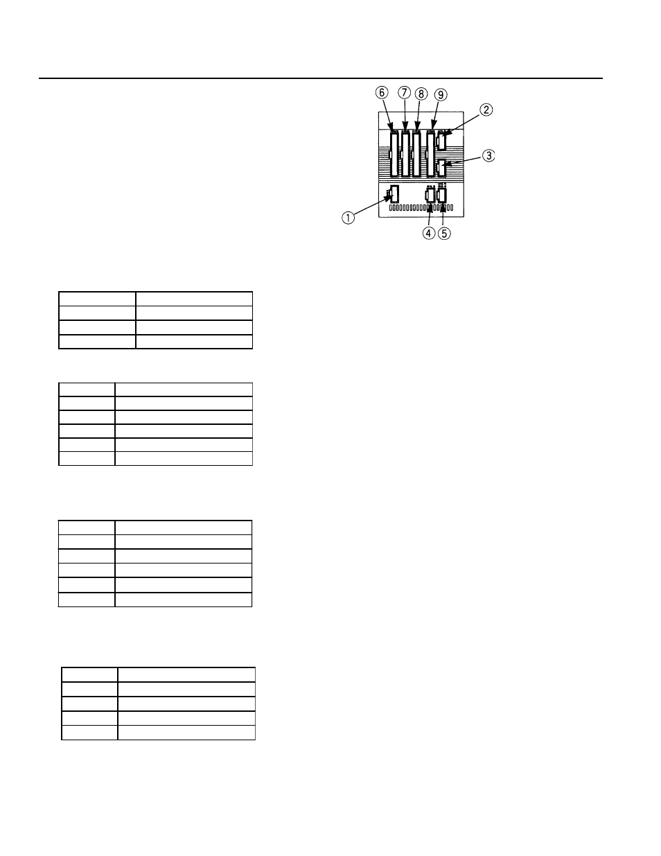
(6) DC100W 4-Axis specifications
Nippon Molex
53258-0520
(5P) (Body side)
51067-0500
Housing (5P)
50217-8100
x 5 Terminal
Nippon Molex
53258-0420
(4P) (Body side)
51067-0400
Housing (4P)
50217-8100
x 4 Terminal
Nippon Molex
53265-0320
(3P) (Body side)
51067-0500
Housing (5P)
50217-8100
x 3 Terminal
Nippon Molex
53258-0520
(5P) (Body side)
51067-0500
Housing (5P)
50217-8100
x 5 Terminal
BK Connector (Option)
* The Emergency Stop is normally open.
LS Connector (Option)
* The Emergency Stop is normally open.
LS Connector (Option)
Power Supply Connector
Pin No.
Signal
1
P24V
2
N
3
ZLS
4
θ
LS
5
EMG stop contact point input*
Pin No.
Signal
1
P24V
2
N
3
XLS
4
YLS
5
EMG stop contact point input*
Pin No.
Signal
1
60V
2
GD
3
XBK
4
YBK
Pin No.
Signal
1
AC117V
3
AC117V
5
FG
This manual is related to the following products: